
Smart-IoT-Sensor-Node

About the Smart-IoT-Sensor-Node PCB
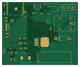
Smart-IoT-Sensor-Node is an open source ESP32 PCB design by harshilgohil989-design, published on GitHub. It is a 2-layer board measuring 83.3 × 69 mm, with 34 components from 27 distinct parts.
Its main chip is the ESP32-C3-WROOM-02-N4, from the ESP32 family. Other key parts include the LM2596S-5.0/NOPB, AP63203WU-7, AM2302, SSD1306 and PC817X1CSZ9F. By type, the board carries 7 capacitors, 7 resistors, 6 ICs, 3 connectors, 3 switches and 3 diodes.
It belongs with the iot & wireless, sensors and displays & leds designs in this gallery.
From the project
WOKWI PROJECT LINK : https://wokwi.com/projects/479480430286401537
WOKWI PROJECT LINK : https://wokwi.com/projects/479480430286401537
An IoT node that reads temperature and humidity, monitors an isolated 24V digital input, controls a relay (locally and over MQTT), and shows live status on an OLED. The project has two parts: a firmware simulation in Wokwi, and a 2-layer PCB designed in KiCad.
- DHT22 temperature and humidity read every 3 s - SSD1306 128x64 OLED: temperature, humidity, input state, relay state, Wi-Fi and MQTT status, uptime - Input read with an interrupt and software debounce (50 ms), no blocking delay() in the main loop - Relay toggled by…
Main components on the Smart-IoT-Sensor-Node
Smart-IoT-Sensor-Node bill of materials (BOM)
34 components, 27 distinct parts — part numbers from the project's BOM.
| Qty | Part | Footprint | Refs |
|---|---|---|---|
| 1 | LM2596S-5.0/NOPB LM2596S-5 | TO-263-5_TabPin3 | U1 |
| 1 | ESP32-C3-WROOM-02-N4 ESP32-C3-WROOM-02 | ESP32-C3-WROOM-02 | U2 |
| 1 | AP63203WU-7 AP63203WU | TSOT-23-6 | U3 |
| 1 | AM2302 DHT22 | ASAIR_AM2302_P2.54mm_Vertical | U4 |
| 1 | SSD1306 | ER_OLEDM0.91_1x-I2C | U5 |
| 1 | PC817X1CSZ9F PC817 | DIP-4_W7.62mm | U6 |
| 1 | BC33725BU Q_NPN_BCE | TO-92_Inline | Q1 |
| 1 | 105017-0001 USB_B_Micro | USB_Micro-B_Molex-105017-0001 | J1 |
| 1 | INPUT | PinHeader_1x02_P2.54mm_Vertical | J2 |
| 1 | Screw_Terminal | TerminalBlock_Phoenix_MKDS-1,5-3_1x03_P5.00mm_Horizontal | J3 |
| 1 | MF-MSMF050-2 Fuse | Fuse_0603_1608Metric | F1 |
| 1 | G5LE-1-DC5 G5LE-1 | Relay_SPDT_Omron-G5LE-1 | K2 |
| 3 | EVQ-P7C01P SW_Push | SW_SPST_EVQP7C | SW1, SW2, SW3 |
| 1 | 1N4148W-7-F D | D_0805_2012Metric | D3 |
| 1 | SMBJ28A D_Zener | D_SOD-123 | D6 |
| 1 | 1N5822 | D_DO-201AD_P15.24mm_Horizontal | D7 |
| 1 | SDR1105-330KL L | L_10.4x10.4_H4.8 | L1 |
| 1 | SRN4018-4R7M L | L_0201_0603Metric | L2 |
| 1 | CL21A106KBQNNNE 10 | C_0805_2012Metric | C1 |
| 1 | UVR1V681MPD 680MICF | C_0805_2012Metric | C2 |
Show 7 more
| Qty | Part | Footprint | Refs |
|---|---|---|---|
| 1 | UVR1C221MED 220 | C_0805_2012Metric | C3 |
| 1 | CL21B104KBCNNNC 100nF | C_0805_2012Metric | C4 |
| 1 | CL21A226MPQNNNE 2 *22 | C_0805_2012Metric | C5 |
| 1 | CL21B104KBCNNNC 10nF | C_0805_2012Metric | C6 |
| 1 | CL21B105KAFNNNE 1microf | C_0805_2012Metric | C8 |
| 6 | RC0805FR-0710KL 10k | R_0805_2012Metric | R1, R2, R3, R5, R6, R7 |
| 1 | RC1206FR-074K7L R | R_0805_2012Metric | R4 |
Smart-IoT-Sensor-Node design files
The KiCad project lives in the harshilgohil989-design/Smart-IoT-Sensor-Node repository on GitHub; these links point at the commit this page was built from.
Smart-IoT-Sensor-Node: common questions
What microcontroller does the Smart-IoT-Sensor-Node use?
The Smart-IoT-Sensor-Node is built around the ESP32-C3-WROOM-02-N4, from the ESP32 family.
How big is the Smart-IoT-Sensor-Node PCB?
The Smart-IoT-Sensor-Node measures 83.3 × 69 mm, has 2 copper layers and is 1.6 mm thick.
How many components are on the Smart-IoT-Sensor-Node?
34 components, from 27 distinct parts, with part numbers taken from the project's own BOM. The full bill of materials is listed on this page.
Where can I download the Smart-IoT-Sensor-Node design files?
From the harshilgohil989-design/Smart-IoT-Sensor-Node repository on GitHub, which has the KiCad layout, the schematic and the BOM; the links under Design files point to each one.
Can I use the Smart-IoT-Sensor-Node design in my own project?
The repository has no license, so all rights stay with harshilgohil989-design. Use it as a reference, and ask the author before reusing the design.
Can I test firmware for the Smart-IoT-Sensor-Node without the hardware?
Yes. HardLabs builds a simulation of the board from its netlist and BOM, so you can run and debug ESP32 firmware against it before you order a PCB.
Similar boards
 ESP32
OSO-BOOK-B1
joeycastillo
85 × 115 mm65 parts2LCC-BY-SA-4.08.1k ESP32
Powertrain
byrantech
64 × 45.4 mm171 parts4LMIT4.3k ESP32
Badge
atopile
56.3 × 39 mm239 parts4LMIT4.0k ESP32
Esp32 minimal
36.2 × 26.8 mm20 parts2LMIT4.0k ESP32
Racer
StuckAtPrototype
36 × 50.2 mm70 parts4LApache-2.03.8k ESP32
Controller
29 × 74 mm58 parts4LApache-2.03.8k