
FCCU-v2-schematic

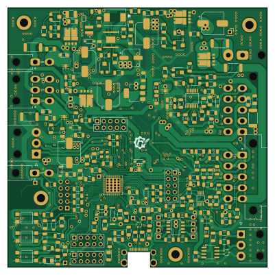
About the FCCU-v2-schematic PCB
FCCU-v2-schematic is an open source ESP32 PCB design by HydrogreenPollub, published on GitHub under the MIT license. It is a 2-layer board measuring 100 × 100 mm, with 213 components from 99 distinct parts.
Its main chip is the ESP32-S3FN8, from the ESP32 family. Other key parts include the LM76202QPWPRQ1, AD8544ARUZ-REEL, ILD206T, ADS1015IDGSR and LM5013DDAR. By type, the board carries 85 resistors, 55 capacitors, 14 connectors, 12 diodes, 10 ICs and 3 transistors.
From the project
New fuel cell control pcb
Main components on the FCCU-v2-schematic
FCCU-v2-schematic bill of materials (BOM)
213 components, 99 distinct parts.
| Qty | Part | Footprint | Refs |
|---|---|---|---|
| 1 | LM76202QPWPRQ1 | SOP65P640X120-17N | IC1 |
| 1 | AD8544ARUZ-REEL | SOP65P640X120-14N | IC2 |
| 1 | ILD206T | SOIC127P610X323-8N | IC3 |
| 1 | ADS1015IDGSR | SOP50P490X110-10N | IC4 |
| 1 | LM5013DDAR | Diodes_SO-8EP | U1 |
| 1 | TPS62933 | SOT-583-8 | U2 |
| 1 | LDI1117-05H | SOT-223-3_TabPin2 | U3 |
| 1 | USBLC6-2P6 | SOT-666 | U5 |
| 1 | ESP32-S3FN8 | QFN-56-1EP_7x7mm_P0.4mm_EP5.6x5.6mm | U6 |
| 1 | SN65HVD232 | SOIC-8_3.9x4.9mm_P1.27mm | U7 |
| 3 | PMPB10XNX | PMPB15XPAX | Q1, Q2, Q3 |
| 1 | Crystal_GND24 | KC3225K400000C1GE00 | Y1 |
| 1 | 9HT7-32.768KDZF-T | 9HT732768KDZFT | Y2 |
| 1 | Supercapacitors | Molex_Mini-Fit_Jr_5569-02A2_2x01_P4.20mm_Horizontal | J1 |
| 1 | CAN | 39303035 | J2 |
| 1 | UART | 39303035 | J3 |
| 1 | P_Valve | Molex_Mini-Fit_Jr_5569-02A2_2x01_P4.20mm_Horizontal | J4 |
| 1 | Button | Molex_Mini-Fit_Jr_5569-02A2_2x01_P4.20mm_Horizontal | J5 |
| 1 | FC Module | Molex_Mini-Fit_Jr_5569-10A1_2x05_P4.20mm_Horizontal | J6 |
| 1 | FC Cooling | Molex_Mini-Fit_Jr_5569-10A1_2x05_P4.20mm_Horizontal | J7 |
Show 79 more
| Qty | Part | Footprint | Refs |
|---|---|---|---|
| 1 | M_Valve | Molex_Mini-Fit_Jr_5569-06A2_2x03_P4.20mm_Horizontal | J8 |
| 1 | NC | PinSocket_2x05_P2.54mm_Vertical | J11 |
| 1 | Analog | PinSocket_2x05_P2.54mm_Vertical | J12 |
| 1 | I/O | PinSocket_2x05_P2.54mm_Vertical | J13 |
| 1 | Top signals | PinSocket_2x05_P2.54mm_Vertical | J14 |
| 1 | Fuel cell signals | PinSocket_2x05_P2.54mm_Vertical | J15 |
| 1 | USB_C_Plug_USB2.0 | 2169900002 | P1 |
| 2 | +5V | PinSocket_1x01_P2.54mm_Vertical | 2x5V, +5V |
| 1 | LDI1117-3.3H | SOT-223-3_TabPin2 | (U4) |
| 1 | +3.3V | PinSocket_1x01_P2.54mm_Vertical | +3V3 |
| 1 | A_1 | PinSocket_1x01_P2.54mm_Vertical | A_1 |
| 1 | A_2 | PinSocket_1x01_P2.54mm_Vertical | A_2 |
| 1 | C_1 | PinSocket_1x01_P2.54mm_Vertical | C_1 |
| 1 | C_2 | PinSocket_1x01_P2.54mm_Vertical | C_2 |
| 1 | E_1 | PinSocket_1x01_P2.54mm_Vertical | E_1 |
| 1 | E_2 | PinSocket_1x01_P2.54mm_Vertical | E_2 |
| 1 | 3A | FUSC8664X180N | F1 3A |
| 1 | K_1 | PinSocket_1x01_P2.54mm_Vertical | K_1 |
| 1 | K_2 | PinSocket_1x01_P2.54mm_Vertical | K_2 |
| 2 | Pot_12V 20k | TC33X2503E | RV1, RV2 |
| 1 | Pot_12V 5k | TC33X2503E | RV3 |
| 2 | Pot_12V 2k | TC33X2503E | RV4, RV5 |
| 1 | Ant | PinSocket_1x01_P2.54mm_Vertical | TP3 |
| 1 | USB_D+ | PinSocket_1x01_P2.54mm_Vertical | TP12 |
| 1 | USB_D- | PinSocket_1x01_P2.54mm_Vertical | TP13 |
| 9 | MMSZ3V3T1G | SOD3716X135N | Z1, Z2, Z3, Z4, Z5, Z6, Z7, Z8 +1 |
| 1 | TPSMC30CA | TPSMCSeries_LTF | D1 |
| 4 | V6K100DUHM3/H V10K100DUHM3_H | V10K100DUHM3H | D2, D3, D4, D5 |
| 1 | SP0502BAJT | SOT-323_SC-70 | D6 |
| 3 | LED | LED_1206_3216Metric | D7, D8, D9 |
| 3 | PMEG10020 | PMEG10020ELR | D10, D11, D12 |
| 1 | IHLP6767DZER470M11 | IHLP6767DZER470M11 | L1 |
| 1 | 4u7 | SRN3015TA4R7M | L2 |
| 6 | 1u | C_1206_3216Metric | C1, C13, C30, C33, C38, C55 |
| 1 | 10u 100V | CP_Elec_8x10.5 | C2 |
| 1 | 2n2 100V | C_1206_3216Metric | C3 |
| 1 | 47u | CP_Elec_6.3x7.7 | C4 |
| 1 | 2n7 | C_1206_3216Metric | C5 |
| 2 | 47p | C_1206_3216Metric | C6, C14 |
| 1 | 3n3 | C_1206_3216Metric | C7 |
| 1 | 1-10u | C_1210_3225Metric_Pad1.33x2.70mm_HandSolder | C8 |
| 2 | 22u | CP_Elec_8x10.5 | C9, C15 |
| 1 | 33n | C_1206_3216Metric | C10 |
| 14 | 100n | C_1206_3216Metric | C11, C12, C18, C23, C25, C27, C31, C32 +6 |
| 1 | 100u | CP_Elec_8x10.5 | C16 |
| 2 | 12p | C_1206_3216Metric | C17, C20 |
| 2 | 1p2 | C_1206_3216Metric | C19, C22 |
| 2 | 20p | C_1206_3216Metric | C21, C24 |
| 2 | 0 | C_1206_3216Metric | C26, C29 |
| 1 | 10u | CP_Elec_8x10.5 | C28 |
| 1 | 10n | C_1206_3216Metric | C34 |
| 7 | c | C_1206_3216Metric | C40, C41, C44, C46, C47, C53, C54 |
| 3 | 4n7 | C_1206_3216Metric | C43, C45, C49 |
| 3 | 20n | C_1206_3216Metric | C50, C51, C52 |
| 2 | 5k1 | R_1206_3216Metric | R1, R4 |
| 2 | 0 | R_1206_3216Metric | R2, R3 |
| 2 | 0R | R_2512_6332Metric | R5_FC, R6_SC |
| 1 | 180k | R_1206_3216Metric | R7 |
| 1 | 12k | R_1206_3216Metric | R8 |
| 3 | 100k | R_1206_3216Metric | R9, R10, R11 |
| 1 | 5k6 | R_1206_3216Metric | R12 |
| 1 | 143k | R_1206_3216Metric | R13 |
| 1 | 453k | R_1206_3216Metric | R14 |
| 1 | 49k9 | R_1206_3216Metric | R15 |
| 1 | 47k | R_1206_3216Metric | R16 |
| 7 | 15k | R_1206_3216Metric | R17, R60, R67, R69, R83, R85, R86 |
| 20 | 10k | R_1206_3216Metric | R18, R19, R21, R23, R24, R31, R40, R41 +12 |
| 1 | 5M | R_1206_3216Metric | R20 |
| 19 | 1k | R_1206_3216Metric | R22, R25, R26, R27, R28, R29, R30, R34 +11 |
| 2 | 100R | R_1206_3216Metric | R32, R33 |
| 1 | 200R | R_1206_3216Metric | R37 |
| 2 | 0R | R_1206_3216Metric | R38, R39 |
| 2 | 6k8 | R_1206_3216Metric | R44, R46 |
| 2 | 3k3 | R_1206_3216Metric | R45, R47 |
| 2 | k | R_1206_3216Metric | R48, R50 |
| 2 | 60 | R_1206_3216Metric | R51, R57 |
| 3 | 2k | R_1206_3216Metric | R70, R80, R81 |
| 3 | 180R | R_1206_3216Metric | R71, R72, R73 |
| 3 | 100R 0,5W | R_2512_6332Metric | R77, R78, R79 |
FCCU-v2-schematic design files
The KiCad project lives in the HydrogreenPollub/pcb-fuel-cell-control repository on GitHub; these links point at the commit this page was built from.
FCCU-v2-schematic: common questions
What microcontroller does the FCCU-v2-schematic use?
The FCCU-v2-schematic is built around the ESP32-S3FN8, from the ESP32 family.
How big is the FCCU-v2-schematic PCB?
The FCCU-v2-schematic measures 100 × 100 mm, has 2 copper layers and is 1.6 mm thick.
How many components are on the FCCU-v2-schematic?
213 components, from 99 distinct parts. The full bill of materials is listed on this page.
Where can I download the FCCU-v2-schematic design files?
From the HydrogreenPollub/pcb-fuel-cell-control repository on GitHub, which has the KiCad layout; the links under Design files point to each one.
Can I use the FCCU-v2-schematic design in my own project?
Yes, under the terms of its MIT license, which HydrogreenPollub chose for the repository.
Can I test firmware for the FCCU-v2-schematic without the hardware?
Yes. HardLabs builds a simulation of the board from its netlist and BOM, so you can run and debug ESP32 firmware against it before you order a PCB.
More boards in pcb-fuel-cell-control
Similar boards
 ESP32
OSO-BOOK-B1
joeycastillo
85 × 115 mm65 parts2LCC-BY-SA-4.08.1k ESP32
Powertrain
byrantech
64 × 45.4 mm171 parts4LMIT4.3k ESP32
Esp32 minimal
atopile
36.2 × 26.8 mm20 parts2LMIT4.0k ESP32
Badge
56.3 × 39 mm239 parts4LMIT4.0k ESP32
Racer
StuckAtPrototype
36 × 50.2 mm70 parts4LApache-2.03.8k ESP32
Controller
29 × 74 mm58 parts4LApache-2.03.8k