
PICO ADC Test

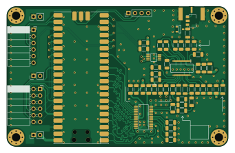
About the PICO ADC Test PCB
PICO ADC Test is an open source RP2040/RP2350 PCB design by kelu124, published on GitHub. It is a 4-layer board measuring 85 × 54 mm, with 55 components from 30 distinct parts.
Its main chip is the MSI2500, from the RP2040/RP2350 family. Other key parts include the ADC10065CIMT/NOPB, AD8331ARQZ, MCP4812-E/MS and MD0100N8-G. By type, the board carries 26 capacitors, 11 resistors, 7 connectors, 5 ICs, 5 inductors and 1 diode.
From the project
OpenSourceHardware - going to MRI
1 dual PMOD, 12ADCbits+1clk + 1SPI (without MISO): based on the AD8331+ADC+DAC from https://github.com/kelu124/lit3rick/ (altium source in hardware folder) . Connector in: SMA, with MD0100 to protect. Possible elements: AD8331 ADC: AD9629BCPZ-65: 12bits, DAC: MCP4812-E/MS
Only logic through PMOD: positivepulse, negativepulse, damp. Expose remaining IOs on a 2.54" rail on the PMOD board (with 3.3V and GND as well) External GPIOs for +HV, -HV, GND. Internal : Positive: 3.3V -> 5V booster ; Negative: -5V rail for example (not mandatory if simpler exists)…
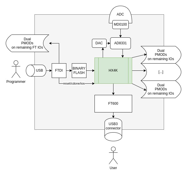
Main components on the PICO ADC Test
PICO ADC Test bill of materials (BOM)
55 components, 30 distinct parts — part numbers from the project's BOM.
| Qty | Part | Footprint | Refs |
|---|---|---|---|
| 1 | ADC10065CIMT/NOPB ADC10065CIMT_NOPB | SOP65P640X120-28N | IC1 |
| 1 | AD8331ARQZ | SOP64P600X175-20N | IC2 |
| 1 | MCP4812-E/MS MCP4812-E_MS | MCP4812-EMS | IC3 |
| 1 | MD0100N8-G | SOT-89-3 | U1 |
| 1 | MSI2500 Pico | RPi_Pico_SMD | U2 |
| 1 | 142-0701-801 AMPHENOL_132357-11 | AMPHENOL_132357-11 | J1 |
| 1 | 22-23-2021 | PinHeader_1x02_P2.54mm_Vertical | J2 |
| 1 | 61300611121 Würth Elektronik | PinSocket_1x06_P2.54mm_Horizontal | J3 |
| 1 | 90122-0126 Conn_01x04 | PinHeader_1x04_P2.54mm_Vertical | J4 |
| 2 | 22-23-2021 | PinHeader_1x02_P2.54mm_Vertical | J5, J7 |
| 1 | 90122-0126 | PinSocket_2x06_P2.54mm_Horizontal | J6 |
| 1 | BAV99-7-F | SOT95P240X120-3N | D1 |
| 5 | BLM21BB750SN1D ILHB1206ER750V | L_1206_3216Metric | FB1, FB2, FB3, FB4, FB5 |
| 11 | VJ1206Y104KXQCW1BC 100nF | C_1206_3216Metric | C1, C2, C5, C9, C10, C11, C17, C19 +3 |
| 2 | 1206ZD475KAT4A 4.7uF | C_1206_3216Metric | C3, C7 |
| 1 | 10UF 100nF | C_1206_3216Metric | C4 |
| 1 | VJ1206Y183KXAAC 18nF | C_1206_3216Metric | C6 |
| 2 | 10NF 100nF | C_1206_3216Metric | C8, C15 |
| 1 | VJ1206A220JXQPW1BC 22pF | C_1206_3216Metric | C12 |
| 2 | 1UF 100nF | C_1206_3216Metric | C13, C16 |
Show 10 more
| Qty | Part | Footprint | Refs |
|---|---|---|---|
| 1 | 18PF 100nF | C_1206_3216Metric | C14 |
| 3 | 1NF 1nF | C_1206_3216Metric | C18, C21, C23 |
| 1 | 10UF 50pF | C_1206_3216Metric | C20 |
| 1 | 10UF 10uF | C_1206_3216Metric | C25 |
| 1 | 18R | R_1206_3216Metric | R1 |
| 4 | 10K | R_1206_3216Metric | R2, R3, R5, R6 |
| 2 | 100R | R_1206_3216Metric | R4, R8 |
| 1 | 280R | R_1206_3216Metric | R7 |
| 1 | 12K | R_1206_3216Metric | R9 |
| 2 | 510R 18R | R_1206_3216Metric | R10, R11 |
PICO ADC Test design files
The KiCad project lives in the kelu124/oshmri repository on GitHub; these links point at the commit this page was built from.
PICO ADC Test: common questions
What microcontroller does the PICO ADC Test use?
The PICO ADC Test is built around the MSI2500, from the RP2040/RP2350 family.
How big is the PICO ADC Test PCB?
The PICO ADC Test measures 85 × 54 mm, has 4 copper layers and is 1.6 mm thick.
How many components are on the PICO ADC Test?
55 components, from 30 distinct parts, with part numbers taken from the project's own BOM. The full bill of materials is listed on this page.
Where can I download the PICO ADC Test design files?
From the kelu124/oshmri repository on GitHub, which has the KiCad layout, the schematic and the BOM; the links under Design files point to each one.
Can I use the PICO ADC Test design in my own project?
The repository has no license, so all rights stay with kelu124. Use it as a reference, and ask the author before reusing the design.
Can I test firmware for the PICO ADC Test without the hardware?
Yes. HardLabs builds a simulation of the board from its netlist and BOM, so you can run and debug RP2040/RP2350 firmware against it before you order a PCB.
More boards in oshmri
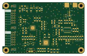
Msi SDR ADC
85 × 54 mm88 parts4LNo license2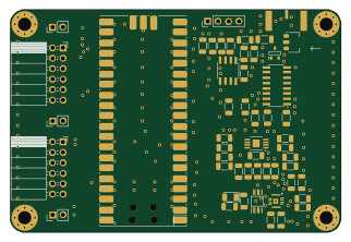 RP2040/RP2350
PicoRX-ADC
80.3 × 54 mm52 parts2LNo license2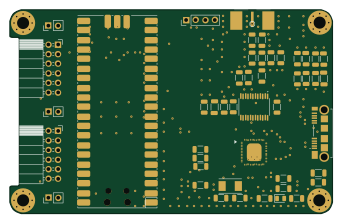 RP2040/RP2350
FT600 RP2040
85.5 × 54 mm47 parts2LNo license2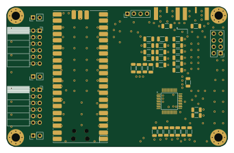 RP2040/RP2350
PICO DAC2932
85.5 × 54 mm42 parts2LNo license2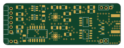
PMOD-Pulser update
63.3 × 22.3 mm33 parts2LNo license2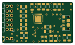
PMOD2USB-FT4222
38.8 × 22.3 mm25 parts2LNo license2
HV-BOARD
20.8 × 22.3 mm8 parts2LNo license2
PMOD2VGA
47.3 × 16.3 mm7 parts2LNo license2
PMOD2PSRAM
18.8 × 16.3 mm4 parts2LNo license2
Similar boards
 RP2040/RP2350
Open Book Abridged Edition
joeycastillo
85 × 115 mm29 parts2LCC-BY-SA-4.08.1k RP2040/RP2350
Corne
foostan
277.2 × 107.5 mm164 parts2LCC-BY-4.07.7k RP2040/RP2350
Corne
277.2 × 107.5 mm164 parts2LCC-BY-4.07.7k RP2040/RP2350
LogicAnalyzer
gusmanb
57 × 55.2 mm6 parts2LGPL-3.05.0k RP2040/RP2350
Jitx design
55.5 × 65 mm26 parts4LGPL-3.05.0k RP2040/RP2350
Pro V2
kata0510
290.1 × 130 mm270 parts2LMIT2.3k