
PiEBV

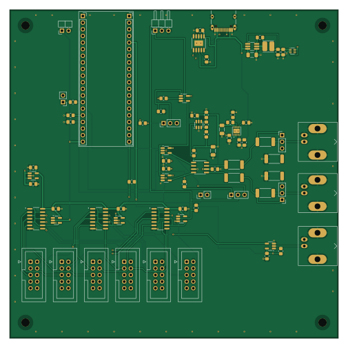
About the PiEBV PCB
PiEBV is an open source RP2040/RP2350 PCB design by Low-Boom, published on GitHub under the GPL-3.0 license. It is a 4-layer board measuring 126 × 126 mm, with 82 components from 50 distinct parts.
Its main chip is the C2905423, from the RP2040/RP2350 family. Other key parts include the 74LVC1G04, SN74LVC04AD, C7826, 74AHCT1G08 and NCP718XSN180. By type, the board carries 24 resistors, 20 capacitors, 18 connectors, 17 ICs, 2 test points and 1 inductor.
From the project
Raspberry Pi Pico 2 Based Light Source and Camera Control for Event-Based Camera Particle Velocimetry
A USB-controlled pulse-timing box for particle image velocimetry (PIV), built around a Raspberry Pi Pico 2 W. It triggers two laser drivers and synchronizes up to six event cameras.
With the assembled board, a Pico 2 W, a USB-C PD charger that supplies 15 V, and a micro-USB data cable:
1. Follow the first-board checks before applying power or connecting equipment. 2. Flash .pio/build/pico2w/firmware.uf2: hold BOOTSEL while connecting the Pico's micro-USB cable, then copy the UF2 to the RP2350 drive. Flash with the Pico out of the board or J17 unplugged. 3. Seat the Pico components-up, USB…
Main components on the PiEBV
PiEBV bill of materials (BOM)
82 components, 50 distinct parts — part numbers from the project's BOM.
| Qty | Part | Footprint | Refs |
|---|---|---|---|
| 2 | 74LVC1G04 | SOT-23-5_HandSoldering | U1, U5 |
| 3 | SN74LVC04AD | SOIC127P600X175-14N | U2, U4, U6 |
| 1 | C7826 74LVC1G00 | SOT-23-5_HandSoldering | U3 |
| 3 | 74AHCT1G08 | SOT-23-5_HandSoldering | U7, U8, U10 |
| 1 | NCP718XSN180 NCP718xSN180 | SOT-23-5_HandSoldering | U9 |
| 1 | 74LVC1G17 | SOT-23-5_HandSoldering | U12 |
| 1 | UCC27524 | SOIC-8_3.9x4.9mm_P1.27mm | U13 |
| 1 | CH224A | SSOP-10-1EP_3.9x4.9mm_P1mm_EP2.1x3.3mm | U14 |
| 1 | AP63205WU | TSOT-23-6_HandSoldering | U15 |
| 1 | LM66100DCK LM66100 | SOT-363_SC-70-6 | U16 |
| 1 | C670143 LT3065EDD | DFN-10-1EP_3x3mm_P0.5mm_EP1.65x2.38mm | U17 |
| 1 | TPS3700DDCR TPS3700DDC | SOT-23-6 | U18 |
| 6 | CONN_02X05_ODD_EVEN Conn_02x05_Odd_Even | IDC-Header_2x05_P2.54mm_Vertical | J1, J2, J3, J4, J5, J6 |
| 1 | C2837587 Laser 1 | BNC_Kinghelm_KH-BNC50-3511_Horizontal | J7 |
| 1 | C2837587 Laser 2 | BNC_Kinghelm_KH-BNC50-3511_Horizontal | J8 |
| 1 | C49257 Trig | PinHeader_1x03_P2.54mm_Vertical | J10 |
| 1 | C49257 Laser Enable | PinHeader_1x03_P2.54mm_Vertical | J11 |
| 1 | C2837587 Pixel Reset | BNC_Kinghelm_KH-BNC50-3511_Horizontal | J12 |
| 1 | C2905423 Pico Socket A | PinSocket_1x20_P2.54mm_Vertical | J14 |
| 1 | C2905423 Pico Socket B | PinSocket_1x20_P2.54mm_Vertical | J15 |
Show 30 more
| Qty | Part | Footprint | Refs |
|---|---|---|---|
| 1 | C32713262 Laser En/PWM Trig/GND | PinHeader_1x03_P2.54mm_Horizontal_EdgeTrim | J16 |
| 1 | C165948 USB-C PD in | USB_C_Receptacle_HRO_TYPE-C-31-M-12_EdgeTrim | J17 |
| 1 | C49257 Laser 1 mode | PinHeader_1x03_P2.54mm_Vertical | J18 |
| 1 | C49257 Laser 2 mode | PinHeader_1x03_P2.54mm_Vertical | J19 |
| 1 | C32713268 Clock jumper | PinHeader_1x02_P2.54mm_Vertical | J20 |
| 1 | C32713261 1MHz sync + GND | PinHeader_1x02_P2.54mm_Horizontal_EdgeTrim | TP3 |
| 1 | C32713268 CH2 monitor + GND | PinHeader_1x02_P2.54mm_Vertical | TP4 |
| 1 | C354587 4.7uH | L_Cenker_CKCS4030 | L1 |
| 9 | C49678 0.1uF | C_0805_2012Metric_Pad1.18x1.45mm_HandSolder | C1, C2, C3, C4, C5, C8, C9, C13 +1 |
| 3 | C28323 1uF | C_0805_2012Metric_Pad1.18x1.45mm_HandSolder | C6, C11, C16 |
| 1 | C28234 2.2uF | C_0805_2012Metric_Pad1.18x1.45mm_HandSolder | C7 |
| 3 | C89632 10uF 50V | C_1206_3216Metric_Pad1.33x1.80mm_HandSolder | C10, C12, C17 |
| 2 | C45783 22uF | C_0805_2012Metric_Pad1.18x1.45mm_HandSolder | C14, C15 |
| 1 | C1729 22nF | C_0805_2012Metric_Pad1.18x1.45mm_HandSolder | C18 |
| 1 | C1710 10nF | C_0805_2012Metric_Pad1.18x1.45mm_HandSolder | C19 |
| 3 | 3K3 3k3 | R_0805_2012Metric_Pad1.20x1.40mm_HandSolder | R2, R3, R5 |
| 2 | C2793964 68 | R_2512_6332Metric_Pad1.40x3.35mm_HandSolder | R6, R7 |
| 5 | 10K 10k | R_0805_2012Metric_Pad1.20x1.40mm_HandSolder | R8, R9, R17, R18, R24 |
| 1 | 56K 56k | R_0805_2012Metric_Pad1.20x1.40mm_HandSolder | R10 |
| 1 | C122537 100k | R_0805_2012Metric_Pad1.20x1.40mm_HandSolder | R12 |
| 1 | C706247 5.36k | R_0805_2012Metric_Pad1.20x1.40mm_HandSolder | R13 |
| 1 | 100K 100k | R_0805_2012Metric_Pad1.20x1.40mm_HandSolder | R16 |
| 1 | 100 | R_0805_2012Metric_Pad1.20x1.40mm_HandSolder | R19 |
| 1 | C17818 750 | R_0805_2012Metric_Pad1.20x1.40mm_HandSolder | R20 |
| 1 | C17470 150k | R_0805_2012Metric_Pad1.20x1.40mm_HandSolder | R21 |
| 1 | C17379 1.2k | R_0805_2012Metric_Pad1.20x1.40mm_HandSolder | R22 |
| 1 | C17673 4.7k | R_0805_2012Metric_Pad1.20x1.40mm_HandSolder | R23 |
| 2 | C7209419 47 | R_2512_6332Metric_Pad1.40x3.35mm_HandSolder | R25, R26 |
| 2 | C7468298 82 | R_2512_6332Metric_Pad1.40x3.35mm_HandSolder | R27, R28 |
| 1 | C17513 1k | R_0805_2012Metric_Pad1.20x1.40mm_HandSolder | R29 |
PiEBV design files
The KiCad project lives in the Low-Boom/PiEBV repository on GitHub; these links point at the commit this page was built from.
- LayoutPiDG_Pico.kicad_pcb
- SchematicPiDG_Pico.kicad_sch
- BOMfab/PiDG_Pico_BOM.csv
PiEBV: common questions
What microcontroller does the PiEBV use?
The PiEBV is built around the C2905423, from the RP2040/RP2350 family.
How big is the PiEBV PCB?
The PiEBV measures 126 × 126 mm, has 4 copper layers and is 1.6 mm thick.
How many components are on the PiEBV?
82 components, from 50 distinct parts, with part numbers taken from the project's own BOM. The full bill of materials is listed on this page.
Where can I download the PiEBV design files?
From the Low-Boom/PiEBV repository on GitHub, which has the KiCad layout, the schematic and the BOM; the links under Design files point to each one.
Can I use the PiEBV design in my own project?
Yes, under the terms of its GPL-3.0 license, which Low-Boom chose for the repository.
Can I test firmware for the PiEBV without the hardware?
Yes. HardLabs builds a simulation of the board from its netlist and BOM, so you can run and debug RP2040/RP2350 firmware against it before you order a PCB.
Similar boards
 RP2040/RP2350
OSO-BOOK-C1
joeycastillo
85 × 115 mm29 parts2LCC-BY-SA-4.08.1k RP2040/RP2350
Corne cherry
foostan
277.2 × 107.5 mm164 parts2LCC-BY-4.07.7k RP2040/RP2350
Corne chocolate
277.2 × 107.5 mm164 parts2LCC-BY-4.07.7k RP2040/RP2350
Jitx design
gusmanb
55.5 × 65 mm26 parts4LGPL-3.05.0k RP2040/RP2350
LogicAnalyzer
57 × 55.2 mm6 parts2LGPL-3.05.0k RP2040/RP2350
Main
google
98 × 71 mm102 parts2LApache-2.02.9k