
Node-Smart-Clock

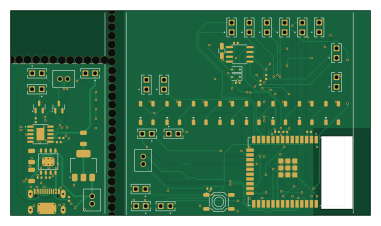
About the Node-Smart-Clock PCB
Node-Smart-Clock is an open source ESP32 PCB design by martinsram3k, published on GitHub. It is a 2-layer board measuring 95 × 54 mm, with 41 components from 19 distinct parts.
Its main chip is the ESP32-WROOM-32D-N4, from the ESP32 family. Other key parts include the CR1220-2, AMS1117-3.3, TP4056, PCF8563T and CH340K. By type, the board carries 11 resistors, 10 diodes, 6 ICs, 6 capacitors, 4 connectors and 2 transistors.
It belongs with the power & battery, sensors and displays & leds designs in this gallery.
From the project
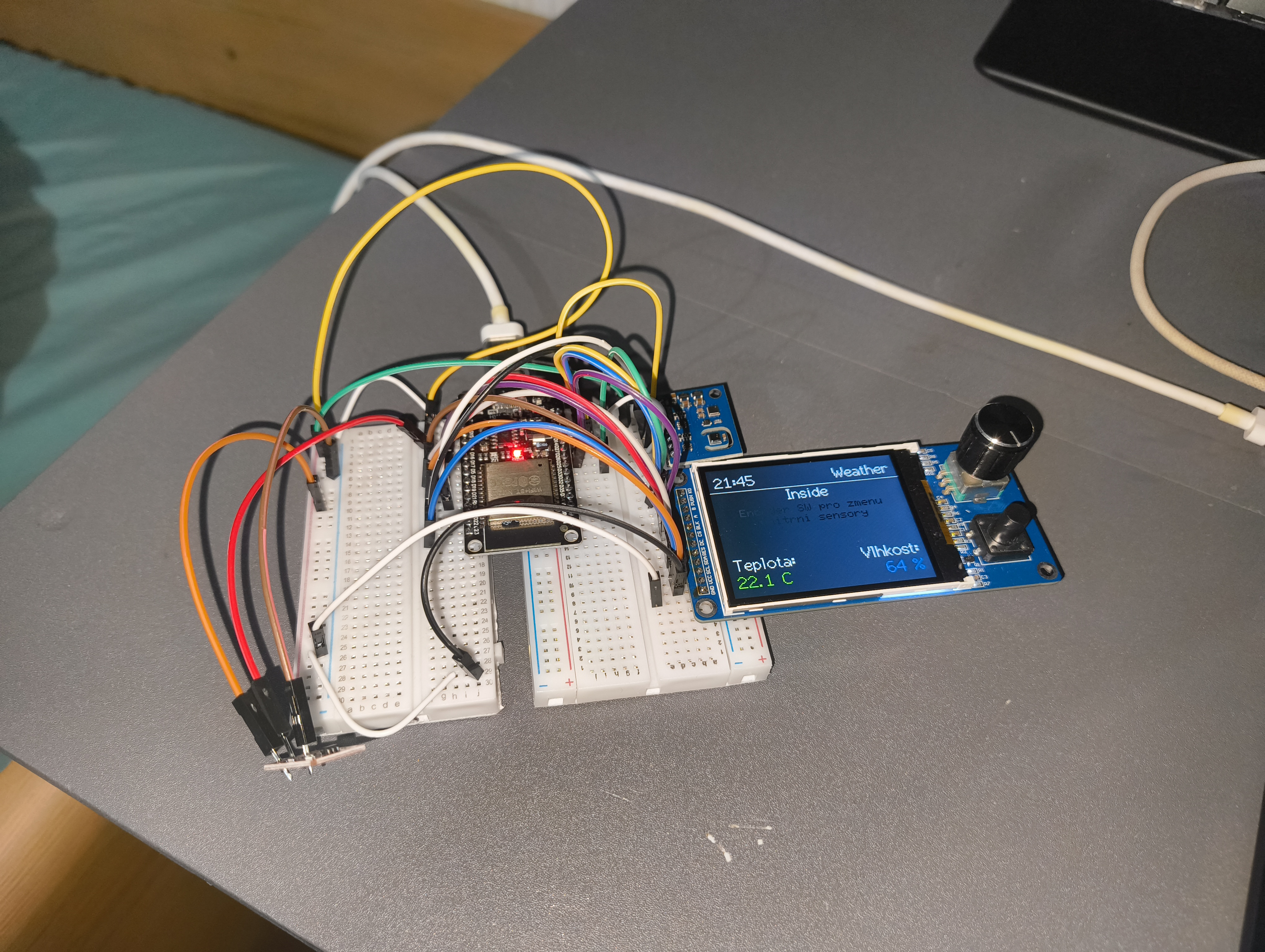
Node Smart Clock is an open-source, multi-functional desk clock powered by the ESP32-WROOM-32D-N4. It is designed as a central hub for makers, entrepreneurs, and crypto enthusiasts, combining advanced environmental sensing with real-time data tracking.
Node Smart Clock is an open-source, multi-functional desk clock powered by the ESP32-WROOM-32D-N4. It is designed as a central hub for makers, entrepreneurs, and crypto enthusiasts, combining advanced environmental sensing with real-time data tracking.
- Environmental Monitoring: Track CO2 levels, Air Quality (ENS160), and temperature in real-time. - Business & Crypto Tracker: Live tracking for cryptocurrency prices, social media follower counts, and Shopify order notifications. - Smart Display: 2.8" TFT display with automatic brightness adjustment based on ambient light (GY-302) to save…
Main components on the Node-Smart-Clock
Node-Smart-Clock bill of materials (BOM)
41 components, 19 distinct parts — part numbers from the project's BOM.
| Qty | Part | Footprint | Refs |
|---|---|---|---|
| 1 | CR1220-2 | Battery_CR1225 | IC1 |
| 1 | ESP32-WROOM-32D-N4 | MODULE_ESP32-WROOM-32D-N4 | U1 |
| 1 | AMS1117-3.3 | SOT-223-3_TabPin2 | U2 |
| 1 | TP4056 TOPPOWER(Nanjing Extension Microelectronics) | ESOP-8_L4.9-W3.9-P1.27-LS6.0-BL-EP | U3 |
| 1 | PCF8563T NXP Semicon | SOIC-8_L5.0-W4.0-P1.27-LS6.0-BL | U4 |
| 1 | CH340K | SSOP-10-1EP_3.9x4.9mm_P1mm_EP2.1x3.3mm | U8 |
| 2 | S8050 MDD(Microdiode Electronics) | Q_SOT-23 | Q2, Q3 |
| 1 | Q13FC1350000400 Seiko Epson | FC-135R_L3.2-W1.5 | X1 |
| 1 | C2927039 Connector, USB-TYPE-C-16P | TYPE-C-SMD_HX-TYPE-C-16PIN | J1 |
| 3 | PHR-2 | JST_PHR-2 | P1, P2, P3 |
| 1 | C318884 Tactile Button, 160gf XKB Connectivity | SW-SMD_4P-L5.1-W5.1-P3.70-LS6.5-TL-2 | S1 |
| 8 | WS2812B | LED_WS2812B_PLCC4_5.0x5.0mm_P3.2mm | D1, D3, D4, D5, D6, D7, D8, D9 |
| 2 | 1N4148WS Changjiang Electronics Tech (CJ) | D_SOD-323 | D11, D12 |
| 3 | 100NF 100nF Samsung Electro-Mechanics | C_0402 | C1, C2, C6 |
| 3 | 10UF 10uF Samsung Electro-Mechanics | C_1206 | C3, C4, C5 |
| 4 | 10kΩ UNI-ROYAL(Uniroyal Elec) | R_0402 | R1, R2, R12, R13 |
| 1 | 100kΩ UNI-ROYAL(Uniroyal Elec) | R_0402 | R3 |
| 5 | 5.1kΩ UNI-ROYAL(Uniroyal Elec) | R_0402 | R4, R5, R9, R10, R11 |
| 1 | 1.2kΩ UNI-ROYAL(Uniroyal Elec) | R_0402 | R6 |
Node-Smart-Clock design files
The KiCad project lives in the martinsram3k/Node-Smart-Clock repository on GitHub; these links point at the commit this page was built from.
Node-Smart-Clock: common questions
What microcontroller does the Node-Smart-Clock use?
The Node-Smart-Clock is built around the ESP32-WROOM-32D-N4, from the ESP32 family.
How big is the Node-Smart-Clock PCB?
The Node-Smart-Clock measures 95 × 54 mm, has 2 copper layers and is 1.6 mm thick.
How many components are on the Node-Smart-Clock?
41 components, from 19 distinct parts, with part numbers taken from the project's own BOM. The full bill of materials is listed on this page.
Where can I download the Node-Smart-Clock design files?
From the martinsram3k/Node-Smart-Clock repository on GitHub, which has the KiCad layout, the schematic and the BOM; the links under Design files point to each one.
Can I use the Node-Smart-Clock design in my own project?
The repository has no license, so all rights stay with martinsram3k. Use it as a reference, and ask the author before reusing the design.
Can I test firmware for the Node-Smart-Clock without the hardware?
Yes. HardLabs builds a simulation of the board from its netlist and BOM, so you can run and debug ESP32 firmware against it before you order a PCB.
Similar boards
 ESP32
ESP32Open Book Abridged Edition
joeycastillo
85 × 115 mm65 parts2LCC-BY-SA-4.08.1k ESP32
ESP32Esp32 minimal
atopile
36.2 × 26.8 mm20 parts2LMIT4.0k ESP32
ESP32Badge
56.3 × 39 mm239 parts4LMIT4.0k ESP32
ESP32Controller
StuckAtPrototype
29 × 74 mm58 parts4LApache-2.03.8k ESP32
ESP32Racer
36 × 50.2 mm70 parts4LApache-2.03.8k ESP32
ESP32Bitaxe
skot
56.5 × 99.8 mm86 parts4LCERN-OHL-S-2.01.4k