
Garage door driver

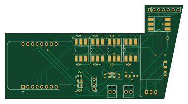
About the Garage door driver PCB
Garage door driver is an open source ESP8266 PCB design by mylife-home, published on GitHub under the GPL-3.0 license. It is a 2-layer board measuring 95 × 50 mm, with 32 components from 14 distinct parts.
Its main chip is the WEMOS_D1_MINI, from the ESP8266 family. Other key parts include the R-785.0-1.0 and 4N35. By type, the board carries 14 resistors, 7 ICs, 5 diodes, 4 connectors and 2 capacitors.
It belongs with the iot & wireless designs in this gallery.
From the project
MyLife Home devices
- doit tenir dans le boitier de la porte ou a côté avec un cable de commande qui sort du boitier - Wifi - alimenté par l'alim de la porte - le plus de contrôle possible - ajouter un capteur de température
- Documentation: https://www.tubauto.fr/app/uploads/2018/02/procom7-3-fr.pdf
- Notes: - 4 borniers à gauche (comme matériel HiFi) - 2 à gauche : alimentation 13V - 2 à droite : poussoir déclencheur externe (24v) - 2 borniers noirs - Sortie (relais d'option) (24v) réglage DIL A=OFF B=ON => fin de course (signal ON si porte fermée, OFF sinon) - 4 borniers à droite - de gauche à droite : 20 -…
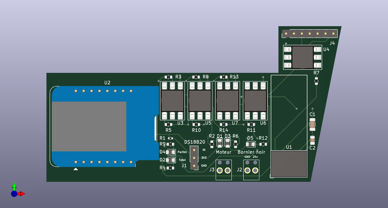
Main components on the Garage door driver
Garage door driver bill of materials (BOM)
32 components, 14 distinct parts — part numbers from the project's BOM.
| Qty | Part | Footprint | Refs |
|---|---|---|---|
| 1 | R-785.0-1.0 | Converter_DCDC_RECOM_R-78E-0.5_THT | U1 |
| 1 | WEMOS_D1_MINI WeMos_D1_mini | WEMOS_D1_mini_light | U2 |
| 5 | 4N35 | DIP-6_W8.89mm_SMDSocket_LongPads | U3, U4, U5, U6, U7 |
| 1 | CONN_01X03_MALE Conn_01x03_Male | PinHeader_1x03_P2.54mm_Vertical | J1 |
| 2 | SCREW_TERMINAL_01X02 Screw_Terminal_01x02 | RS PRO Terminal Small x2 | J2, J3 |
| 1 | CONN_01X07_PIN Conn_01x07_Pin | PinHeader_1x07_P2.54mm_Vertical | J4 |
| 5 | LED | D_0805_2012Metric | D1, D2, D3, D4, D5 |
| 1 | C417124 10μF/50V | C_1206_3216Metric | C1 |
| 1 | C92814 22μF/10V | C_0805_2012Metric | C2 |
| 1 | 4.7KΩ | R_0402_1005Metric | R1 |
| 5 | 1KΩ | R_0603_1608Metric | R2, R4, R6, R9, R12 |
| 3 | 10KΩ | R_0603_1608Metric | R3, R8, R13 |
| 3 | 2.2KΩ | R_0603_1608Metric | R5, R10, R14 |
| 2 | 220Ω | R_0603_1608Metric | R7, R11 |
Garage door driver design files
The KiCad project lives in the mylife-home/mylife-home-devices repository on GitHub; these links point at the commit this page was built from.
Garage door driver: common questions
What microcontroller does the Garage door driver use?
The Garage door driver is built around the WEMOS_D1_MINI, from the ESP8266 family.
How big is the Garage door driver PCB?
The Garage door driver measures 95 × 50 mm, has 2 copper layers and is 1.6 mm thick.
How many components are on the Garage door driver?
32 components, from 14 distinct parts, with part numbers taken from the project's own BOM. The full bill of materials is listed on this page.
Where can I download the Garage door driver design files?
From the mylife-home/mylife-home-devices repository on GitHub, which has the KiCad layout, the schematic and the BOM; the links under Design files point to each one.
Can I use the Garage door driver design in my own project?
Yes, under the terms of its GPL-3.0 license, which mylife-home chose for the repository.
Can I test firmware for the Garage door driver without the hardware?
Yes. HardLabs builds a simulation of the board from its netlist and BOM, so you can run and debug ESP8266 firmware against it before you order a PCB.
More boards in mylife-home-devices
Epanel energy monitor
103 × 86.5 mm143 parts2LGPL-3.00 ESP32
ESP32Prototype-3
100 × 100 mm68 parts2LGPL-3.00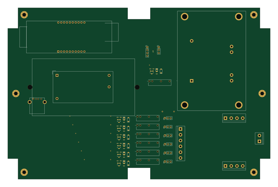 ESP32
ESP32Garden box
230 × 150 mm66 parts2LGPL-3.00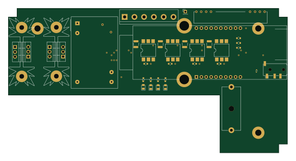 ESP32
ESP32Bed smart plug
145 × 75 mm37 parts2LGPL-3.00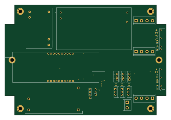 ESP32
ESP32Rgb garden box
149.3 × 102 mm37 parts2LGPL-3.00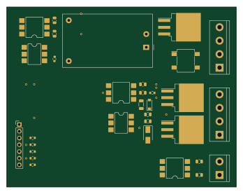
Prototype-2
87 × 68 mm32 parts2LGPL-3.00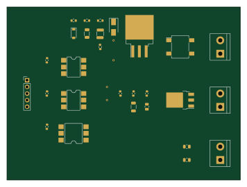
Prototype
88.9 × 66 mm28 parts2LGPL-3.00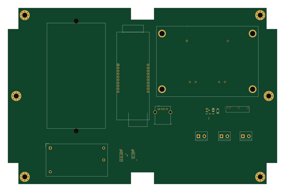 ESP32
ESP32Prototype-1
230 × 150 mm17 parts2LGPL-3.00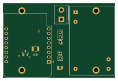 ESP8266
Clim driver
60 × 40 mm10 parts2LGPL-3.00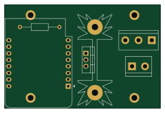 ESP8266
Fairy lights
60 × 40 mm6 parts2LGPL-3.00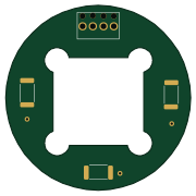
Rgb spot-10w
45 × 45 mm5 parts2LGPL-3.00
Similar boards
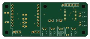 ESP8266
ESP8266ControllerCircuit
stuartpittaway
75 × 30 mm20 parts2LCC-BY-NC-4.01.1k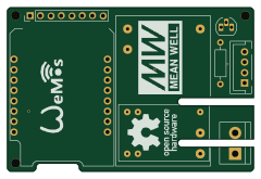 ESP8266
HASwitchPlate
aderusha
60 × 40 mm8 parts2LMIT738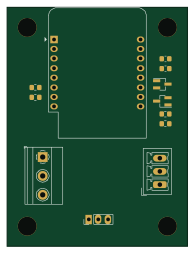 ESP8266
RatGDO-OpenSource-D1Mini-ESP8266
Kaldek
47.8 × 63.3 mm12 parts2LMIT506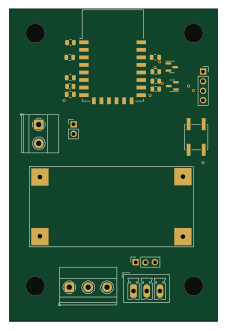 ESP8266
RatGDO-OpenSource-Bare-ESP8266
55 × 82.7 mm20 parts2LMIT506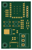 ESP8266
Goatgdo
32.9 × 53.3 mm23 parts2LMIT506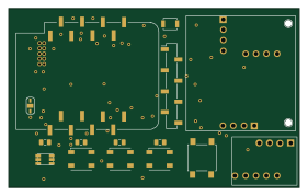 ESP8266
Iaq board
nkitanov
70.1 × 43.2 mm17 parts2LNo license398