
Main-Board

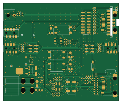
About the Main-Board
Main-Board is an open source PCB design by open-headset-interconnect-standard, published on GitHub under the CC-BY-4.0 license. It is a 2-layer board measuring 100 × 84 mm, with 146 components from 40 distinct parts.
Other key parts include the LM78M05_TO252, LP5907MFX-2.5, LM4808, NJM4580 and LTV-217-B-G. By type, the board carries 60 capacitors, 29 inductors, 29 resistors, 9 connectors, 5 ICs and 4 test points.
It belongs with the rf & radio and audio designs in this gallery.
From the project
An open-source OHIS Radio Adapter.
As of 2024-07-17, this is a Work In Progress.
1. Design a set of circuits that can be used to build OHIS compliant radio adapters. 2. Designs should be as simple as possible, but no simpler. 3. When laying out boards, keep as many parts through-hole as possible for ease of assembly. 4. There are two types of designs here: 1. General: Has all the circuits required to work with any radio, that needs to be configured. 2. Radio Specific: Trades Configurability for Simplicity. Make a simpler device for a specific radio.
Main components on the Main-Board
Main-Board bill of materials (BOM)
146 components, 40 distinct parts.
| Qty | Part | Footprint | Refs |
|---|---|---|---|
| 1 | LM78M05_TO252 | TO-252-2 | U1 |
| 1 | LP5907MFX-2.5 | SOT-23-5 | U2 |
| 1 | LM4808 | SOP-8_3.76x4.96mm_P1.27mm | U3 |
| 1 | NJM4580 | SOP-8_3.76x4.96mm_P1.27mm | U4 |
| 1 | LTV-217-B-G | SO-4_4.4x2.3mm_P1.27mm | U5 |
| 1 | OHIS Radio Port | Conn_RJ45_SMT_Amphenol-RJCSE-538X | J2 |
| 1 | Radio Mic RJ45 | Conn_RJ45_SMT_Amphenol-RJCSE-538X | J3 |
| 1 | Mic Pinout Config | PinHeader_2x08_P2.54mm_Vertical_SMD | J4 |
| 1 | GX16 Riser | Conn_B2B-RA_2.54mm_9pin_Full-Slot | J5 |
| 1 | Radio Mic 3.5mm | Conn_3.5mm-PJ-393-8_SMT-C668609 | J6 |
| 2 | CTIA/Headphones | PinHeader_2x03_P2.54mm_Vertical_SMD | J7, J11 |
| 1 | Radio Headphone/Speaker Front | Conn_3.5mm-PJ-393-8_SMT-C668609 | J8 |
| 1 | Radio Headphone/Speaker Rear | Conn_3.5mm-PJ-393-8_SMT-C668609 | J10 |
| 1 | 0.5A | Fuse_1206_3216Metric | F1 |
| 1 | 200mA | Fuse_0805_2012Metric | F2 |
| 3 | 1k | Potentiometer_Bourns_3314J_Vertical | RV1, RV2, RV3 |
| 1 | HP Left Transformer | Transformer_ED8_4-Lead_10.5x8mm_P5mm | T1 |
| 1 | HP Right Transformer | Transformer_ED8_4-Lead_10.5x8mm_P5mm | T2 |
| 1 | Mic Transformer | Transformer_ED8_4-Lead_10.5x8mm_P5mm | T3 |
| 1 | +12v | TestPoint_THTPad_D1.5mm_Drill0.7mm | TP1 |
Show 20 more
| Qty | Part | Footprint | Refs |
|---|---|---|---|
| 1 | +5v | TestPoint_THTPad_D1.5mm_Drill0.7mm | TP2 |
| 1 | +2.5v | TestPoint_THTPad_D1.5mm_Drill0.7mm | TP3 |
| 1 | GND | TestPoint_THTPad_D1.5mm_Drill0.7mm | TP4 |
| 1 | SS34 | D_SMA | D1 |
| 1 | Green LED | LED_0805_2012Metric | D2 |
| 29 | RF Choke | L_0805_2012Metric | FB1, FB2, FB3, FB4, FB5, FB6, FB7, FB8 +21 |
| 8 | 0.1uF | C_0603_1608Metric | C1, C3, C4, C37, C39, C49, C50, C54 |
| 1 | 0.33uF | C_0603_1608Metric | C2 |
| 5 | 47uF | C_0805_2012Metric | C5, C9, C41, C53, C56 |
| 9 | 1uF | C_0603_1608Metric | C6, C8, C38, C40, C45, C46, C51, C52 +1 |
| 1 | 47uF | CP_Elec_6.3x5.8 | C7 |
| 27 | 100pF | C_0603_1608Metric | C10, C11, C12, C13, C14, C15, C16, C17 +19 |
| 2 | 470uF | CP_Elec_6.3x7.7 | C26, C34 |
| 6 | 330pF | C_0603_1608Metric | C35, C36, C44, C47, C59, C60 |
| 1 | 10uF | C_0603_1608Metric | C48 |
| 10 | 1k | R_0603_1608Metric | R1, R2, R11, R12, R13, R14, R20, R21 +2 |
| 3 | 100R | R_0603_1608Metric | R3, R4, R19 |
| 8 | 10k | R_0603_1608Metric | R5, R7, R8, R10, R15, R17, R24, R26 |
| 6 | 33k | R_0603_1608Metric | R6, R9, R16, R18, R25, R27 |
| 2 | 0R | R_0603_1608Metric | R28, R29 |
Main-Board design files
The KiCad project lives in the open-headset-interconnect-standard/radio-adapter repository on GitHub; these links point at the commit this page was built from.
Main-Board: common questions
How big is the Main-Board?
The Main-Board measures 100 × 84 mm, has 2 copper layers and is 1.6 mm thick.
How many components are on the Main-Board?
146 components, from 40 distinct parts. The full bill of materials is listed on this page.
Where can I download the Main-Board design files?
From the open-headset-interconnect-standard/radio-adapter repository on GitHub, which has the KiCad layout and the schematic; the links under Design files point to each one.
Can I use the Main-Board design in my own project?
Yes, under the terms of its CC-BY-4.0 license, which open-headset-interconnect-standard chose for the repository.
More boards in radio-adapter
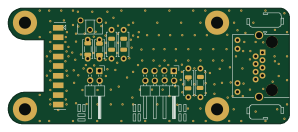
BaseBoard
74.3 × 30.5 mm35 parts2LCC-BY-4.05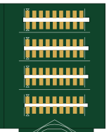
GX16-8P-Horizontal Slot Test
38.1 × 47 mm22 parts2LCC-BY-4.05
Icom-GX16
27.3 × 38.1 mm5 parts2LCC-BY-4.05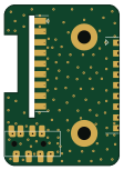
Yaesu-GX16
27.3 × 38.1 mm5 parts2LCC-BY-4.05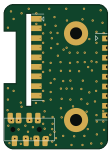
Kenwood-GX16
27.3 × 38.1 mm5 parts2LCC-BY-4.05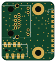
Icom-RJ45
27.3 × 30.5 mm3 parts2LCC-BY-4.05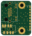
Kenwood-RJ45
27.3 × 30.5 mm3 parts2LCC-BY-4.05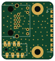
Yaesu-RJ45
27.3 × 30.5 mm3 parts2LCC-BY-4.05
Yaesu-6p6c
27.3 × 30.5 mm3 parts2LCC-BY-4.05
Similar boards
KLOR
GEIGEIGEIST
160.2 × 118.3 mm79 parts2LGPL-3.01.2k
USB
shanteacontrols
52 × 12.6 mm6 parts2LApache-2.0956
ButtonsLEDs
390 × 37 mm82 parts2LApache-2.0956
Pots
390 × 93 mm75 parts2LApache-2.0956
PicoGUS Hand386
polpo
29.2 × 75.2 mm43 parts4LGPL-2.0800
Snark barker
schlae
231.1 × 106.7 mm193 parts2LNo license687