
Pcb

About the Pcb
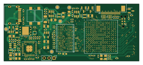
Pcb is an open source RP2040/RP2350 PCB design by openconcepts-ar, published on GitHub under the Custom license license. It is a 4-layer board measuring 69.6 × 29.4 mm, with 154 components from 47 distinct parts.
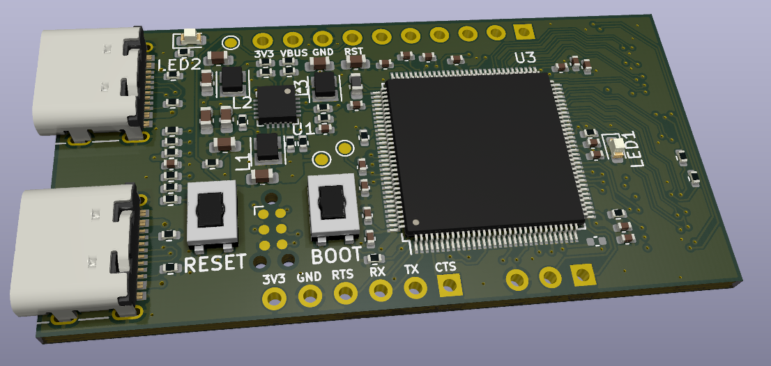
Its main chip is the RP2040, from the RP2040/RP2350 family. Other key parts include the SY8120IABC, MT9700, XC6SLX16-FTG256, MT9700-N and MT41K64M16TW. By type, the board carries 77 capacitors, 47 resistors, 10 ICs, 7 connectors, 4 inductors and 3 transistors.
From the project
Here are the design files for the current 11 boards of this project:
Here are the design files for the current 11 boards of this project:
Processing boards: CPU board ECP5 FPGA board * Spartan-6 FPGA board
Adapter boards: eDP adapter board VGA adapter & connector LVDS adapters single and dual channel DVI adapter * DVI passive adapter
Debugging boards: DVI receiver Touch splitter * I/O board
It features: C906 64-bit RISC-V CPU @1GHz (22nm manufacturing process) Integrated 64MB DDR2 RAM Small size, breadboard compatible SD card socket to store media assets 2 USB-C connectors with Host and OTG (Host/Device) functions, respectively Video output connector…
Main components on the Pcb
Pcb bill of materials (BOM)
154 components, 47 distinct parts.
| Qty | Part | Footprint | Refs |
|---|---|---|---|
| 3 | SY8120IABC SY8120 | SOT-23-6 | U1, U2, U3 |
| 1 | MT9700 | SOT-23-5 | U4 |
| 1 | XC6SLX16-FTG256 | Xilinx_FTG256 | U5 |
| 1 | MT9700-N | SOT-23-5 | U6 |
| 1 | MT41K64M16TW | BGA-96_9.0x14.0mm_P0.8mm | U12 |
| 1 | W25Q32JV | WSON-8-1EP_6x5mm_P1.27mm_EP3.4x4.3mm | U13 |
| 1 | RP2040 | RP2040-QFN-56 | U14 |
| 1 | USBLC6-2P6 | SOT-666-6_L1.6-W1.2-P0.50-LS1.6-BR | U15 |
| 3 | AO3400A | SOT-23 | Q3, Q4, Q5 |
| 1 | 3N24000G33YC 33MHz | Oscillator_SMD_Abracon_ASE-4Pin_3.2x2.5mm | Y1 |
| 1 | X322512MSB4SI 12MHz | Oscillator_SMD_Abracon_ASE-4Pin_3.2x2.5mm | Y2 |
| 1 | TYPE-C-31-M-12 USB_C_Receptacle_USB2.0 | USB_C_Receptacle_HRO_TYPE-C-31-M-12 | J1 |
| 1 | SWD | PinHeader_1x03_P2.54mm_Vertical | J5 |
| 2 | DF12NB(3.0)-30DS-0.5V(51) | DF12NB3030DP05V51 | J6, J7 |
| 1 | PRT-12807 JTAG | Tag-Connect_TC2030-IDC-NL_2x03_P1.27mm_Vertical | J8 |
| 1 | F0501-B-20-20T-R Conn_01x20 | FPC-SMD_20P-P0.50_L4.4-W15.6 | J9 |
| 1 | TF-018 TF TF-018 1.5mm | TF-SMD_TF-018 | J10 |
| 2 | TS-1007S-AR02516 | SW_SPST_CK_RS282G05A3 | SW1, SW2 |
| 2 | RCLAMP0524P | Diodes_UDFN-10_1.0x2.5mm_P0.5mm | D9, D10 |
| 1 | BLM15AG601SN1D 600R | L_0402_1005Metric | FB1 |
Show 27 more
| Qty | Part | Footprint | Refs |
|---|---|---|---|
| 3 | FTC201610S4R7MBCA | L_Murata_DFE201610P | L1, L2, L3 |
| 11 | 10uF 10V | C_0805_2012Metric | C1, C2, C3, C7, C14, C15, C16, C17 +3 |
| 18 | 100nF | C_0402_1005Metric | C4, C5, C6, C8, C9, C10, C87, C88 +10 |
| 3 | 47pF | C_0402_1005Metric | C11, C12, C13 |
| 36 | 220nF | C_0402_1005Metric | C18, C19, C20, C21, C22, C24, C25, C26 +28 |
| 4 | 22uF | C_0603_1608Metric | C23, C33, C84, C85 |
| 2 | 1uF | C_0402_1005Metric | C89, C102 |
| 2 | 18pF | C_0402_1005Metric | C92, C93 |
| 1 | 47uF 10V | C_1206_3216Metric | C103 |
| 2 | 5.1K 1% | R_0402_1005Metric | R1, R2 |
| 1 | 91K 1% | R_0402_1005Metric | R3 |
| 2 | 20K 1% | R_0402_1005Metric | R4, R5 |
| 2 | 16K 1% | R_0402_1005Metric | R6, R7 |
| 1 | 27K 1% | R_0402_1005Metric | R8 |
| 2 | 10K 1% | R_0402_1005Metric | R9, R19 |
| 11 | 4.7K | R_0402_1005Metric | R10, R12, R13, R14, R16, R18, R38, R40 +3 |
| 3 | 27R | R_0402_1005Metric | R11, R58, R59 |
| 4 | 1K 1% | R_0402_1005Metric | R15, R43, R44, R55 |
| 1 | 6K2 1% | R_0402_1005Metric | R17 |
| 2 | 0R | R_0402_1005Metric | R35, R36 |
| 2 | 100R 1% | R_0402_1005Metric | R37, R39 |
| 1 | 240R 1% | R_0402_1005Metric | R41 |
| 8 | 51R | R_0402_1005Metric | R45, R46, R47, R49, R50, R51, R53, R54 |
| 2 | 1K | R_0402_1005Metric | R56, R57 |
| 1 | 120K 1% | R_0402_1005Metric | R60 |
| 1 | 240K 1% | R_0402_1005Metric | R61 |
| 1 | 4D02WGJ0103TCE 10K | R_Array_Convex_4x0402 | RN1 |
Pcb design files
The KiCad project lives in the openconcepts-ar/accel2d repository on GitHub; these links point at the commit this page was built from.
Pcb: common questions
What microcontroller does the Pcb use?
The Pcb is built around the RP2040, from the RP2040/RP2350 family.
How big is the Pcb?
The Pcb measures 69.6 × 29.4 mm, has 4 copper layers and is 1.01 mm thick.
How many components are on the Pcb?
154 components, from 47 distinct parts. The full bill of materials is listed on this page.
Where can I download the Pcb design files?
From the openconcepts-ar/accel2d repository on GitHub, which has the KiCad layout and the schematic; the links under Design files point to each one.
Can I use the Pcb design in my own project?
It is published under Custom license, which limits how it may be reused; read the license before building on it.
Can I test firmware for the Pcb without the hardware?
Yes. HardLabs builds a simulation of the board from its netlist and BOM, so you can run and debug RP2040/RP2350 firmware against it before you order a PCB.
More boards in accel2d
 RP2040/RP2350
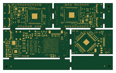
Panelized-4layer
114.6 × 70.2 mm209 parts4LCustom license1 FPGA
FPGAOrange Crab
51.2 × 25.8 mm153 parts6LCustom license1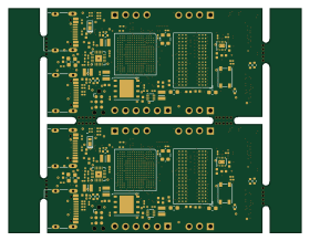 FPGA
FPGAPanelized-6layer
70 × 53.6 mm143 parts6LCustom license1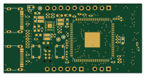
CPU board
51.2 × 25.8 mm103 parts4LCustom license1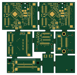
Panelized-2layer
74.6 × 73.2 mm81 parts2LCustom license1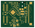
EDP Adapter board
36.3 × 28.4 mm72 parts2LCustom license1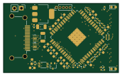
DVI receiver
43 × 25.8 mm52 parts4LCustom license1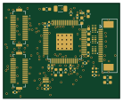
DVI Adapter board
34.6 × 28.4 mm49 parts2LCustom license1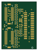
VGA Adapter board
19.2 × 25.8 mm36 parts2LCustom license1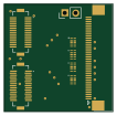
LVDS adapter (2-ch)
26.1 × 25.8 mm8 parts2LCustom license1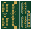
IO board
26.8 × 25.8 mm6 parts2LCustom license1
Similar boards
 RP2040/RP2350
Open Book Abridged Edition
joeycastillo
85 × 115 mm29 parts2LCC-BY-SA-4.08.1k RP2040/RP2350
Corne
foostan
277.2 × 107.5 mm164 parts2LCC-BY-4.07.7k RP2040/RP2350
Corne
277.2 × 107.5 mm164 parts2LCC-BY-4.07.7k RP2040/RP2350
LogicAnalyzer
gusmanb
57 × 55.2 mm6 parts2LGPL-3.05.0k RP2040/RP2350
Jitx design
55.5 × 65 mm26 parts4LGPL-3.05.0k RP2040/RP2350
Pro V2
kata0510
290.1 × 130 mm270 parts2LMIT2.3k