
ChainlinkDriverTester

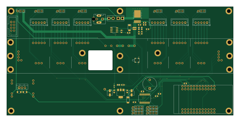
About the ChainlinkDriverTester PCB
ChainlinkDriverTester is an open source PCB design by orgTestCodacy11KRepos110MB, published on GitHub under the Apache-2.0 license. It is a 2-layer board measuring 198.1 × 95.3 mm, with 123 components from 41 distinct parts.
Other key parts include the AP7361C-33E, TTGO_TDisplay, VN7007ALH, MCP23017_SS and INA219BxD. By type, the board carries 64 test points, 22 connectors, 13 resistors, 8 capacitors, 7 ICs and 5 diodes.
It belongs with the wearables and displays & leds designs in this gallery.
From the project
This is a DIY split-flap display. Prototype four-character display: video.
This is a DIY split-flap display. Prototype four-character display: video.
The goal is to make a low-cost display that's easy to fabricate at home in small/single quantities (e.g. custom materials can be ordered from Ponoko or similar, and other hardware is generally available).
You can view an interactive 3d model of the design on the project website.
The splitflap community Discord server is the best place to keep up with the latest changes or ask questions about the project!

Main components on the ChainlinkDriverTester
ChainlinkDriverTester bill of materials (BOM)
123 components, 41 distinct parts.
| Qty | Part | Footprint | Refs |
|---|---|---|---|
| 1 | AP7361C-33E | SOT-223-3_TabPin2 | U1 |
| 1 | TTGO_TDisplay | T-DISPLAY_extra_pins | U2 |
| 1 | VN7007ALH | VN7007ALHTR | U3 |
| 1 | MCP23017_SS | SSOP-28_5.3x10.2mm_P0.65mm | U4 |
| 1 | INA219BxD | SOIC-8_3.9x4.9mm_P1.27mm | U5 |
| 1 | LM7805_TO220 | TO-220-3_Vertical | U6 |
| 1 | Buck | BuckModuleBackSilk | U7 |
| 1 | Barrel_Jack_Switch | PJ-202A | J1 |
| 1 | Conn_01x03_Female | PinSocket_1x03_P2.54mm_Vertical | J2 |
| 1 | Motor A | JST_XH_B5B-XH-A_1x05_P2.50mm_Vertical | J3 |
| 1 | Motor B | JST_XH_B5B-XH-A_1x05_P2.50mm_Vertical | J5 |
| 1 | Motor C | JST_XH_B5B-XH-A_1x05_P2.50mm_Vertical | J6 |
| 1 | Motor D | JST_XH_B5B-XH-A_1x05_P2.50mm_Vertical | J7 |
| 1 | Sensor A | PinHeader_1x03_P2.54mm_Vertical | J8 |
| 1 | Sensor B | PinHeader_1x03_P2.54mm_Vertical | J9 |
| 1 | Sensor C | PinHeader_1x03_P2.54mm_Vertical | J10 |
| 1 | Sensor D | PinHeader_1x03_P2.54mm_Vertical | J11 |
| 1 | Motor E | JST_XH_B5B-XH-A_1x05_P2.50mm_Vertical | J12 |
| 1 | Motor F | JST_XH_B5B-XH-A_1x05_P2.50mm_Vertical | J13 |
| 1 | Sensor E | PinHeader_1x03_P2.54mm_Vertical | J14 |
Show 21 more
| Qty | Part | Footprint | Refs |
|---|---|---|---|
| 1 | Sensor F | PinHeader_1x03_P2.54mm_Vertical | J15 |
| 1 | Power | Generic-5.08-2P | J22 |
| 6 | exp | PinHeader_1x04_P2.54mm_Vertical | J26, J27, J28, J29, J30, J31 |
| 1 | Conn_02x04_Odd_Even | IDC-Header_2x04_P2.54mm_Vertical | J101 |
| 1 | Buzzer | Buzzer_12x9.5RM7.6 | BZ1 |
| 1 | 50mA (0ZCM0005FF2G) | Fuse_0603_1608Metric | F1 |
| 1 | Fuse Holder BK-6013 | BK-6013 | F2 |
| 1 | SW_Push | ESE13V01D | SW1 |
| 64 | TestPoint | pogo1mm | TP1, TP2, TP3, TP4, TP5, TP6, TP7, TP8 +56 |
| 3 | Red | LED_0805_2012Metric_Silkscreen | D1, D2, D4 |
| 2 | 2A 500mV | D_SOD-128 | D3, D7 |
| 2 | 10uF | CP_Elec_4x5.3 | C1, C5 |
| 2 | 4.7uF | C_0805_2012Metric | C2, C4 |
| 1 | 10uF | C_1206_3216Metric | C3 |
| 2 | 0.1uF | C_0805_2012Metric | C6, C7 |
| 1 | 22uF | C_1206_3216Metric | C8 |
| 3 | 1k | R_0805_2012Metric | R1, R2, R8 |
| 5 | 15k | R_0805_2012Metric | R3, R4, R5, R6, R10 |
| 3 | 220 | R_0805_2012Metric | R7, R11, R13 |
| 1 | 2k | R_0805_2012Metric | R9 |
| 1 | 0.01R 1% 1W | R_0612_1632Metric | R12 |
ChainlinkDriverTester design files
The KiCad project lives in the orgTestCodacy11KRepos110MB/repo-1066-splitflap repository on GitHub; these links point at the commit this page was built from.
ChainlinkDriverTester: common questions
How big is the ChainlinkDriverTester PCB?
The ChainlinkDriverTester measures 198.1 × 95.3 mm, has 2 copper layers and is 1.6 mm thick.
How many components are on the ChainlinkDriverTester?
123 components, from 41 distinct parts. The full bill of materials is listed on this page.
Where can I download the ChainlinkDriverTester design files?
From the orgTestCodacy11KRepos110MB/repo-1066-splitflap repository on GitHub, which has the KiCad layout; the links under Design files point to each one.
Can I use the ChainlinkDriverTester design in my own project?
Yes, under the terms of its Apache-2.0 license, which orgTestCodacy11KRepos110MB chose for the repository.
More boards in repo-1066-splitflap
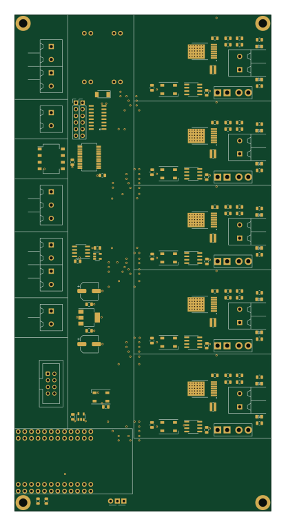
ChainlinkBase
98.4 × 190.5 mm119 parts2LApache-2.00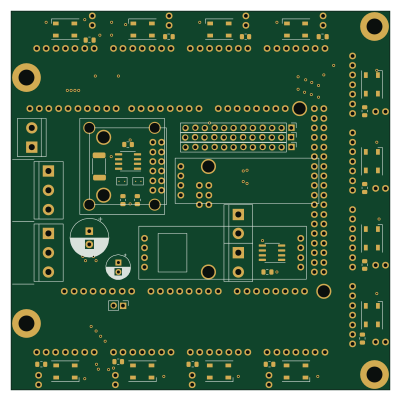
ModuleDriver
100 × 100 mm59 parts2LApache-2.00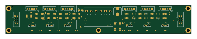
ChainlinkDriver
198.1 × 30.5 mm58 parts2LApache-2.00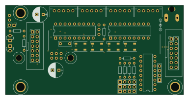 AVR/Arduino
Splitflap controller board
96 × 48 mm33 parts2LApache-2.00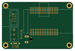
ChainlinkBuddyTDisplay
74.9 × 49.5 mm8 parts2LApache-2.00
Similar boards
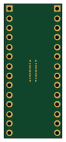
BM28B0.6-24DSBreakout
scottbez1
15.2 × 35.6 mm3 parts2LApache-2.022.2k
LevelShifterBreakout
15.2 × 20.3 mm5 parts2LApache-2.022.2k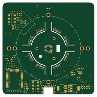
View base
81.2 × 81.2 mm81 parts2LApache-2.022.2k
View screen
35 × 35 mm12 parts2LApache-2.022.2k
Display eval
byrantech
52.1 × 22.6 mm12 parts4LMIT4.3k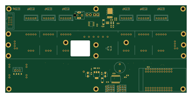
ChainlinkDriverTester
198.1 × 95.3 mm123 parts2LApache-2.04.2k