
23 open source boards using the INA219BxD
Real designs built with the INA219BxD, from public GitHub projects: a quick way to see how others power, decouple and connect it. Each board comes with its KiCad files, full parts list and a render — and you can simulate its firmware on HardLabs.
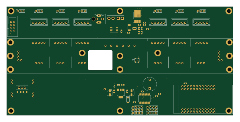
ChainlinkDriverTester
scottbez1
198.1 × 95.3 mm123 parts2LApache-2.04.2k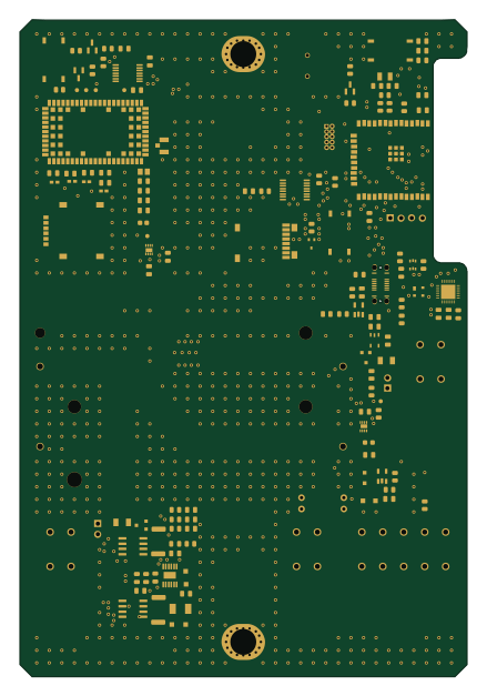 ESP32
Enviro node
DPIclimate
106.7 × 156.6 mm133 parts2LMIT4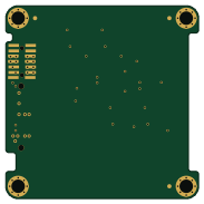
Batteryboard bottom
PyCubed-Mini
45.6 × 45.6 mm49 parts2LNo license3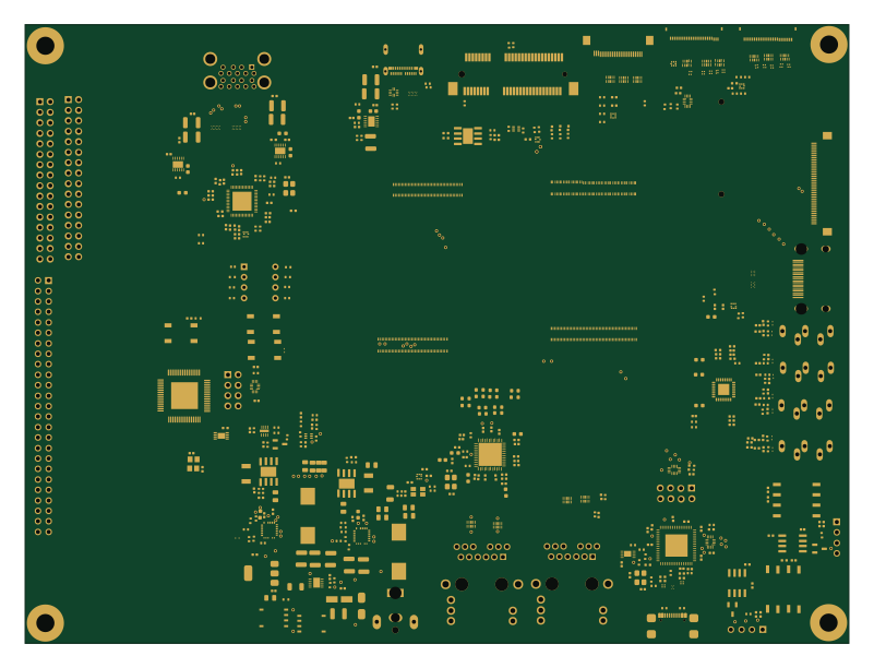 STM32
Base Board Design
WilliamSanchez
199.8 × 150 mm492 parts4LNo license2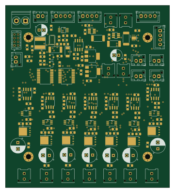
Eps
UWCubeSat
89.4 × 99.3 mm165 parts2LNo license2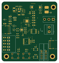 STM32
USB C PD
JBeeBK
60 × 64.9 mm78 parts4LNo license1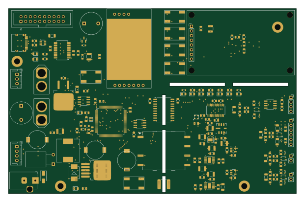 STM32
ANCP Rocket Motor Test Station
jmh8231-Dev
155 × 100 mm281 parts6LNo license0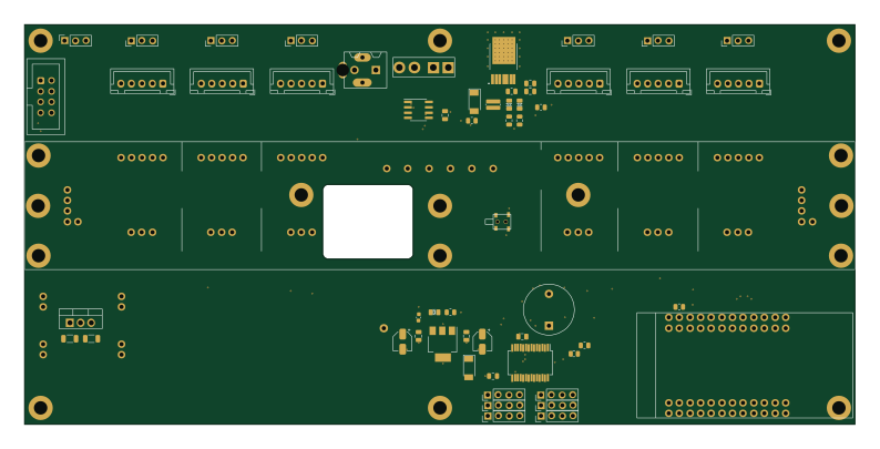
ChainlinkDriverTester
kiwonbyun
198.1 × 95.3 mm123 parts2LApache-2.00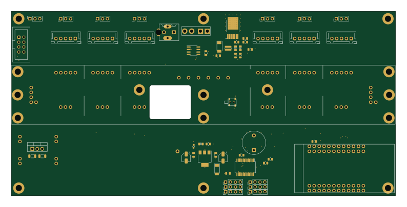
ChainlinkDriverTester
orgTestCodacy11KRepos110MB
198.1 × 95.3 mm123 parts2LApache-2.00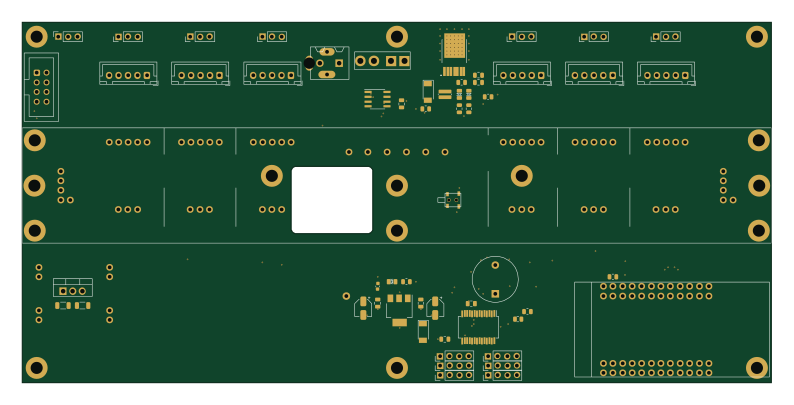
ChainlinkDriverTester
nintando64
198.1 × 95.3 mm123 parts2LApache-2.00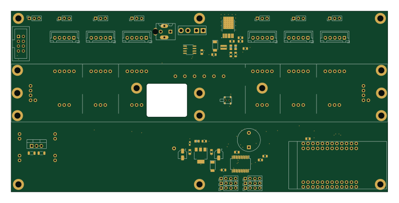
ChainlinkDriverTester
rossbb
198.1 × 95.3 mm123 parts2LApache-2.00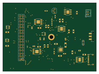
Power sub systems
Eng-Claire
82 × 60 mm48 parts2LNo license0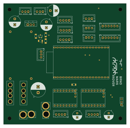 ESP32
Drill
BrnoMarsRover
105 × 103 mm44 parts2LNo license0- schematic only · 369 partsRaspberry Pi
PiCubed
NeilKhera
369 parts2LNo license0 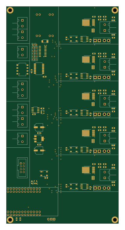
ChainlinkBase
98.4 × 190.5 mm119 parts2LApache-2.04.2k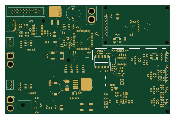 STM32
Solid Rocket Motor Test Station
142.5 × 94.5 mm234 parts6LNo license0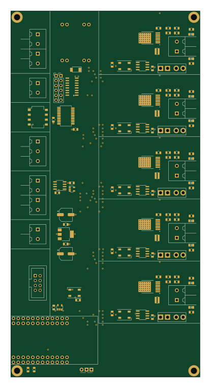
ChainlinkBase
98.4 × 190.5 mm119 parts2LApache-2.00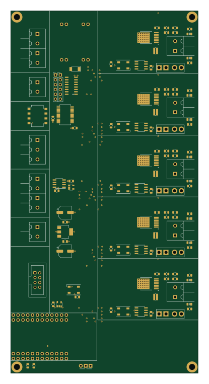
ChainlinkBase
98.4 × 190.5 mm119 parts2LApache-2.00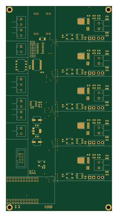
ChainlinkBase
98.4 × 190.5 mm119 parts2LApache-2.00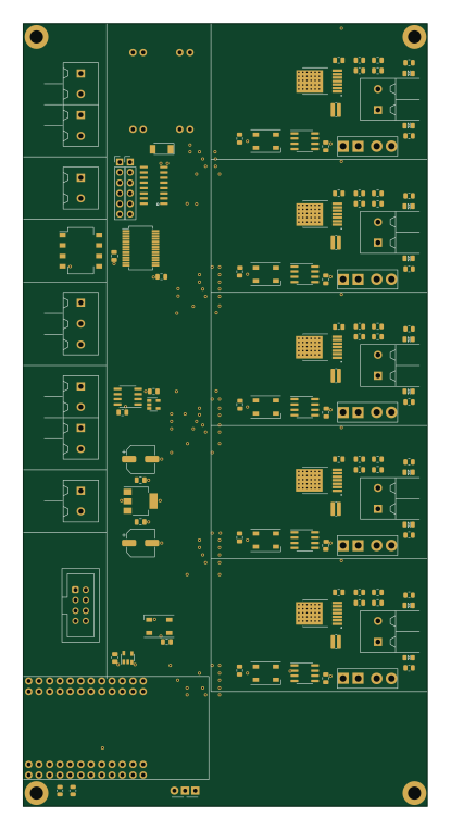
ChainlinkBase
98.4 × 190.5 mm119 parts2LApache-2.00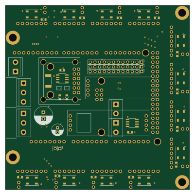
ModuleDriver
100 × 100 mm59 parts2LApache-2.00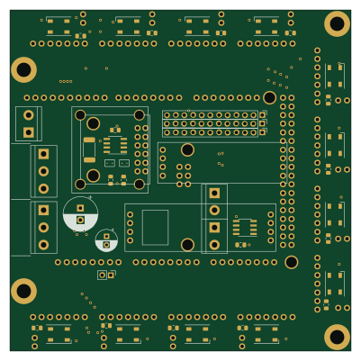
ModuleDriver
100 × 100 mm59 parts2LApache-2.00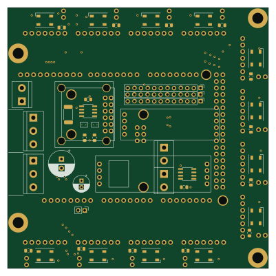
ModuleDriver
100 × 100 mm59 parts2LApache-2.00
How designs wire the INA219BxD
Read from the KiCad layouts of 13 open source designs, one per repository: what each pin of the INA219BxD connects to, and the resistors, capacitors and other passives placed on it.
- The SDA pin has a pull-up to 3.3V on 13 of 13 designs, most often 1 kΩ (then 4.7 kΩ).
- The SCL pin has a pull-up to 3.3V on 13 of 13 designs, most often 1 kΩ (then 4.7 kΩ).
- The VS pin has a decoupling capacitor on 10 of 13 designs, most often 100 nF.
- The A0 pin is tied to GND on 11 of 13 designs.
| Pin | Connected to | Parts on the pin |
|---|---|---|
| A1pin 1 | Connected to: GND 77% · 3.3V 15% | — |
| A0pin 2 | Connected to: GND 85% | — |
| SDApin 3 | Connected to: INA219BxD 54%, MCP23017_SS 38%, TTGO_TDisplay 38% |
|
| SCLpin 4 | Connected to: INA219BxD 54%, MCP23017_SS 38%, TTGO_TDisplay 38% |
|
| VSpin 5 | Connected to: 3.3V 92% |
|
| GNDpin 6 | Connected to: GND 100% | — |
| IN-pin 7 | Connected to: VN7007ALH 38% · BATT 15% |
|
| IN+pin 8 | Connected to: Signal 92% |
|
Connections count pins, parts count designs; values in brackets are how many parts had that value. Designs read include ChainlinkBase by scottbez1, Enviro node by DPIclimate, Batteryboard bottom by PyCubed-Mini and Eps by UWCubeSat.
The INA219BxD in open source designs
The gallery holds 23 open source boards using the INA219BxD from 14 GitHub repositories; a typical one measures about 100 × 100 mm and carries around 119 components.
83% are two-layer designs, the rest use four layers or more, and 61% carry an open source license.
The most starred is ChainlinkDriverTester by scottbez1.
Parts used alongside the INA219BxD
Microcontrollers on boards using the INA219BxD
What boards using the INA219BxD are built for
INA219BxD: common questions
Where can I find a INA219BxD reference design?
Each of the 23 boards on this page is a real design using the INA219BxD. Open one to see how it is wired up, with the full BOM, a render of the layout and links to its KiCad files.
What pull-up resistor is used on the INA219BxD SDA pin?
The SDA pin has a pull-up to 3.3V on 13 of 13 designs, most often 1 kΩ (then 4.7 kΩ). Counted from the KiCad layouts of 13 open source designs using the INA219BxD.
What pull-up resistor is used on the INA219BxD SCL pin?
The SCL pin has a pull-up to 3.3V on 13 of 13 designs, most often 1 kΩ (then 4.7 kΩ). Counted from the KiCad layouts of 13 open source designs using the INA219BxD.
What decoupling capacitors do designs use on the INA219BxD VS pin?
The VS pin has a decoupling capacitor on 10 of 13 designs, most often 100 nF. Counted from the KiCad layouts of 13 open source designs using the INA219BxD.
What parts are used alongside the INA219BxD?
The AP7361C-33E, Buck, LM7805_TO220, MCP23017_SS and SN74LV1T34DBV appear in the most repositories here.
Which microcontrollers do boards using the INA219BxD use?
Most are built on STM32 (4), ESP32 (2) and Raspberry Pi (1).
How big is a typical board using the INA219BxD?
The median is 100 × 100 mm, and 83% are two-layer designs.
What is the most popular open source board using the INA219BxD?
By GitHub stars, ChainlinkDriverTester by scottbez1, with 4,156 stars.
Can I simulate one of these boards using the INA219BxD before building it?
Yes. HardLabs turns a board's netlist and BOM into a working simulation, so you can boot and test firmware against it with no hardware on your desk.