
42 open source boards using the MCP23017_SS
Real designs built with the MCP23017_SS, from public GitHub projects: a quick way to see how others power, decouple and connect it. Each board comes with its KiCad files, full parts list and a render — and you can simulate its firmware on HardLabs.
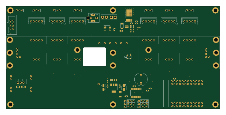
ChainlinkDriverTester
scottbez1
198.1 × 95.3 mm123 parts2LApache-2.04.2k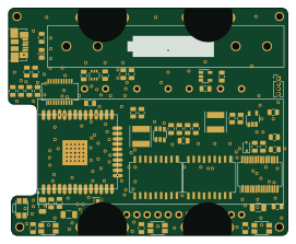 ESP32
VFD Watch
Pakue95
67.8 × 55 mm59 parts2LNo license41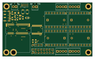
MmStep
luni64
81 × 49 mm32 parts2LMIT14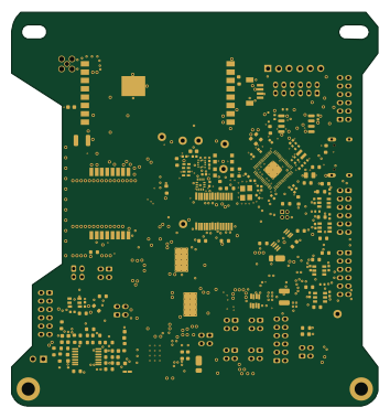 RP2040/RP2350
FC V5d Pro Rev1
proveskit
88 × 94.5 mm255 parts4LCERN-OHL-W-2.06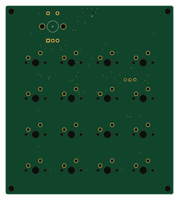 AVR/Arduino
MacroKeyboard
joshajohnson
89 × 100 mm73 parts2LNo license4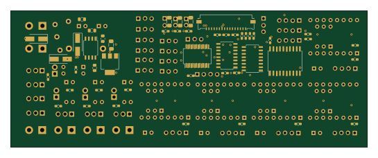
Driver
m24h
136 × 52 mm113 parts2LNo license3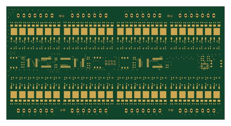
BoneIO - external board
boneIO-eu
197 × 102 mm394 parts2LGPL-3.02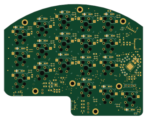 Nordic nRF
Sudi keyboard
ahsanu123
123.4 × 99.4 mm134 parts2LMIT2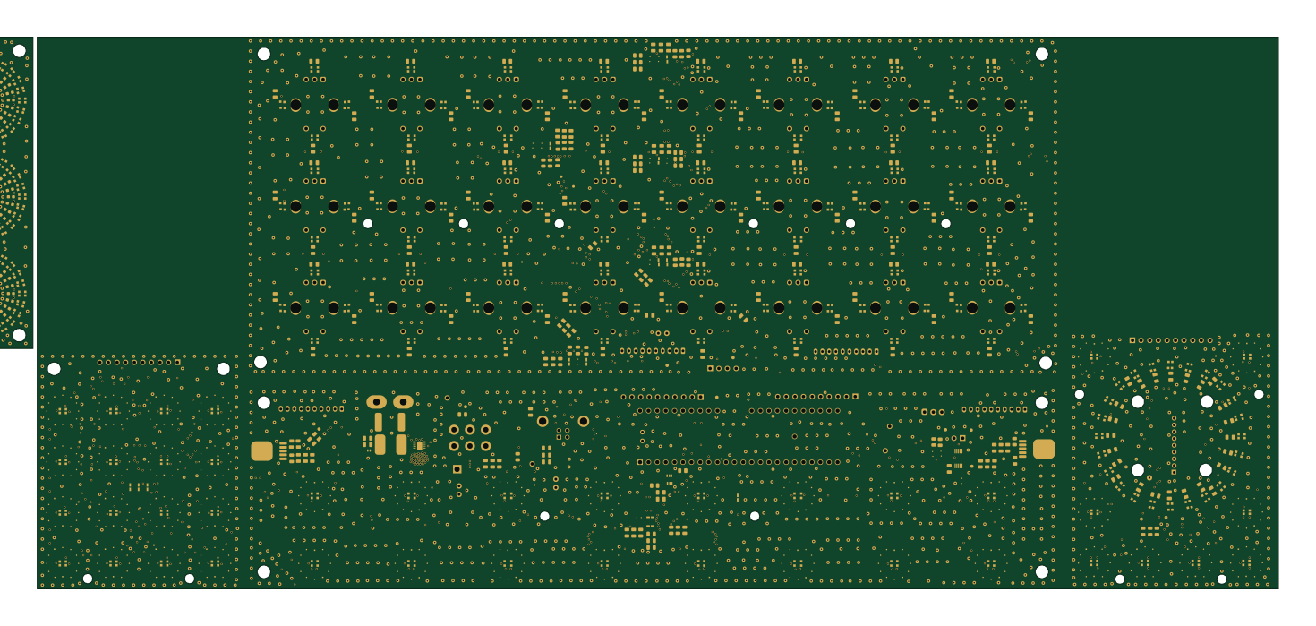
LightPad v1
PaulSalz
367 × 163 mm745 parts2LMIT1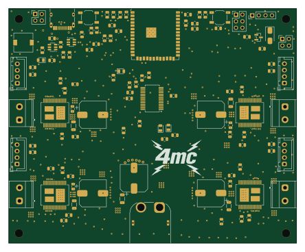 ESP32
Four motor controller
jonathanrandall
110.9 × 90.6 mm113 parts4LCERN-OHL-P-2.01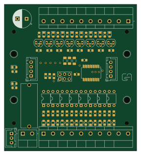
SHIO88E
csabaala
71.5 × 79.5 mm69 parts2LGPL-3.01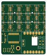
Solo Mini Controller
sullyjason
38 × 45.3 mm35 parts4LNo license1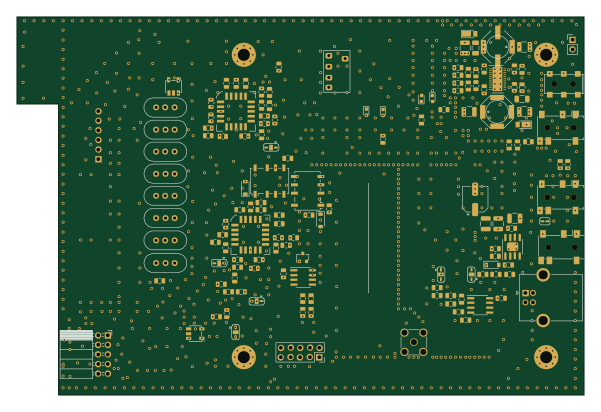
Ssb85
zoonman
150 × 100 mm351 parts2LNo license0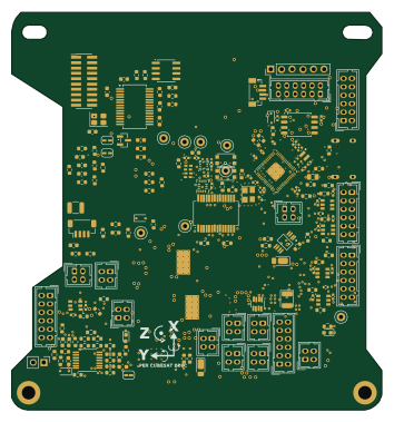 RP2040/RP2350
FC V5d LTM
dpiresearch
88 × 94.5 mm280 parts4LNo license0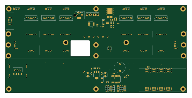
ChainlinkDriverTester
kiwonbyun
198.1 × 95.3 mm123 parts2LApache-2.00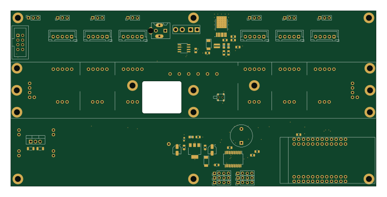
ChainlinkDriverTester
rossbb
198.1 × 95.3 mm123 parts2LApache-2.00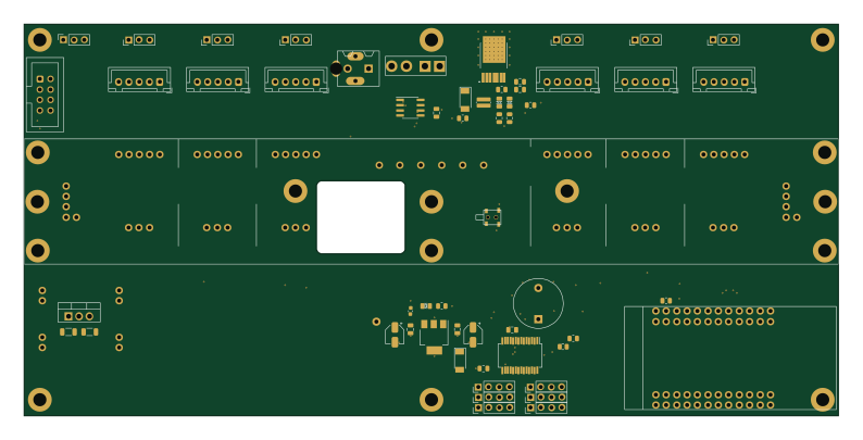
ChainlinkDriverTester
nintando64
198.1 × 95.3 mm123 parts2LApache-2.00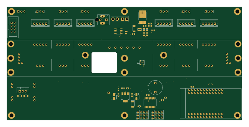
ChainlinkDriverTester
orgTestCodacy11KRepos110MB
198.1 × 95.3 mm123 parts2LApache-2.00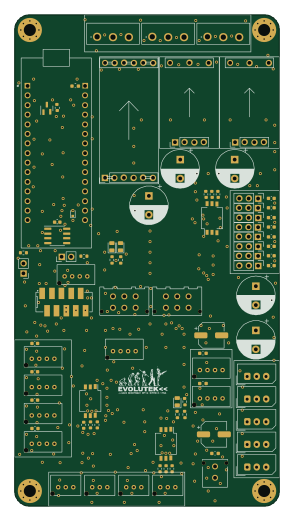
V2
evolutek
70 × 130 mm121 parts2LNo license0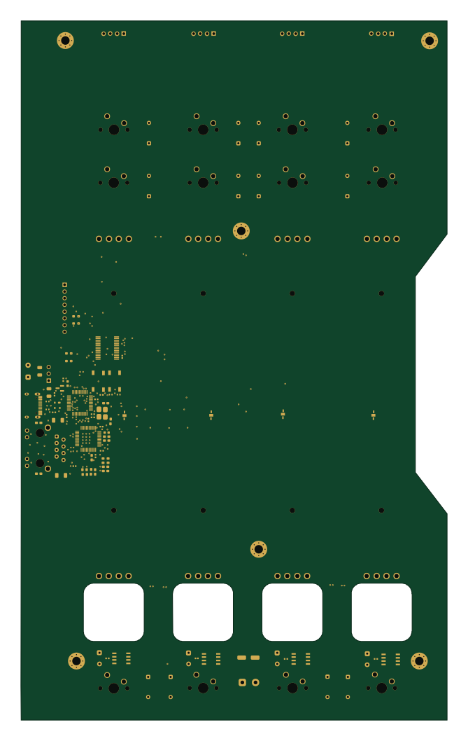 STM32
Fader-Module
KiloanTV
161.1 × 264 mm101 parts4LNo license0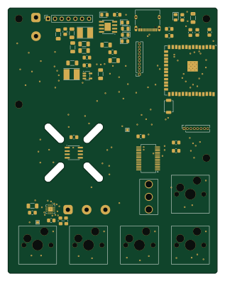 ESP32
Si4
aliadnani
78 × 99 mm57 parts4LNo license0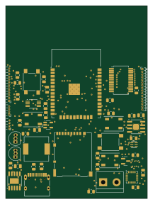 ESP32
ESPBoosted
schoolllex
52.8 × 71.8 mm51 parts2LNo license0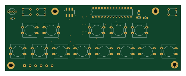
PortaMid
boomninjavanish
152.9 × 57.2 mm23 parts2LLGPL-3.00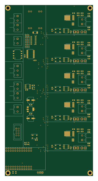
ChainlinkBase
98.4 × 190.5 mm119 parts2LApache-2.04.2k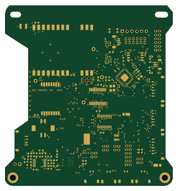 RP2040/RP2350
FC V5e Production Rev1
88 × 94.5 mm244 parts4LCERN-OHL-W-2.06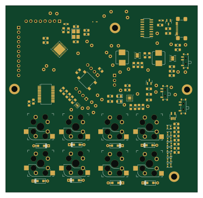 Nordic nRF
Minions
102.1 × 99.1 mm101 parts2LMIT2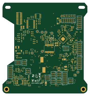 RP2040/RP2350
FC V5d LTM mods 20261010
88 × 94.5 mm280 parts4LNo license0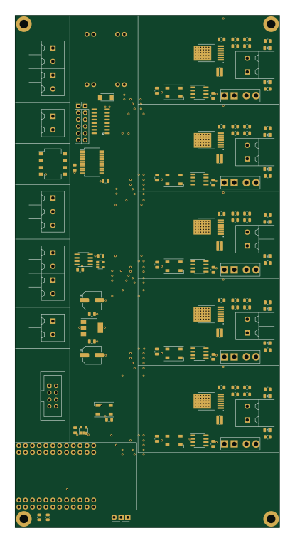
ChainlinkBase
98.4 × 190.5 mm119 parts2LApache-2.00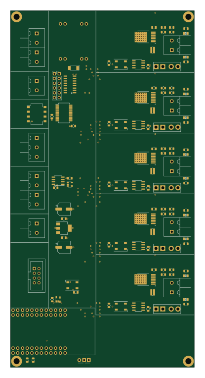
ChainlinkBase
98.4 × 190.5 mm119 parts2LApache-2.00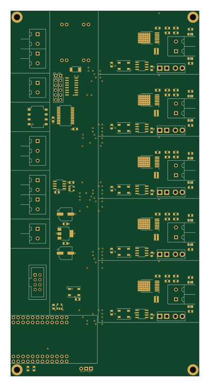
ChainlinkBase
98.4 × 190.5 mm119 parts2LApache-2.00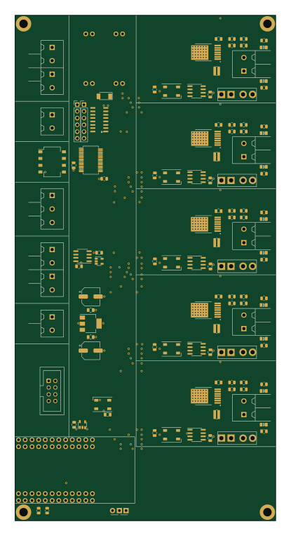
ChainlinkBase
98.4 × 190.5 mm119 parts2LApache-2.00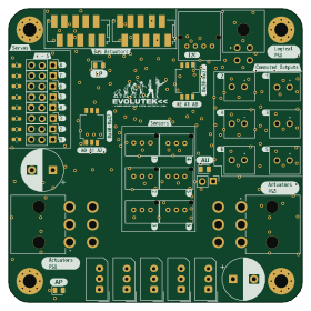
Carte actionneurs
70 × 70 mm115 parts2LNo license0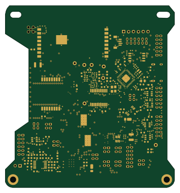 RP2040/RP2350
FC V5d Production Rev2
88 × 94.5 mm243 parts4LCERN-OHL-W-2.06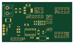 AVR/Arduino
Control
krzys9876
62.7 × 35.6 mm40 parts2LMIT0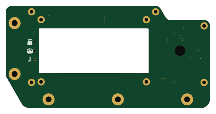
StepUP lcd
Govish
180 × 90 mm27 parts2LNo license0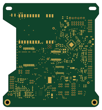 RP2040/RP2350
FC V5e
88 × 94.5 mm242 parts4LCERN-OHL-W-2.06
How designs wire the MCP23017_SS
Read from the KiCad layouts of 28 open source designs, one per repository: what each pin of the MCP23017_SS connects to, and the resistors, capacitors and other passives placed on it.
- The SDA pin has a pull-up to 3.3V on 18 of 28 designs, most often 4.7 kΩ (then 1 kΩ).
- The SCK pin has a pull-up to 3.3V on 17 of 28 designs, most often 4.7 kΩ (then 1 kΩ).
- The INTB pin is left unconnected on 20 of 28 designs (a signal on 8).
- The VDD pin has a decoupling capacitor on 16 of 28 designs, most often 100 nF (then 1 µF).
| Pin | Connected to | Parts on the pin |
|---|---|---|
| VDDpin 9 | Connected to: 3.3V 86% |
|
| VSSpin 10 | Connected to: GND 96% | — |
| NCpin 11, 14 | Connected to: Not connected 96% | — |
| SCKpin 12 | Connected to: A connector 57%, the microcontroller 29% |
|
| SDApin 13 | Connected to: A connector 61%, the microcontroller 29% |
|
| RESETpin 18 | Connected to: Signal 75% · 3.3V 21% |
|
| INTBpin 19 | Connected to: Not connected 71% · a signal 29% | — |
| GPA2pin 23 | Connected to: A connector 29% |
|
| GPA4pin 25 | Connected to: A connector 25% · not connected 18% |
|
| GPA5pin 26 | Connected to: A connector 25% |
|
17 more pins vary from design to design. Connections count pins, parts count designs; values in brackets are how many parts had that value. Designs read include ChainlinkBase by scottbez1, Zynth encoder power display fan by zynthian, VFD Watch by Pakue95 and MmStep by luni64.
The MCP23017_SS in open source designs
The gallery holds 42 open source boards using the MCP23017_SS from 28 GitHub repositories; a typical one measures about 88.5 × 94.5 mm and carries around 117 components.
76% are two-layer designs, the rest use four layers or more, and 62% carry an open source license.
The most starred is ChainlinkDriverTester by scottbez1.
Parts used alongside the MCP23017_SS
Microcontrollers on boards using the MCP23017_SS
What boards using the MCP23017_SS are built for
MCP23017_SS: common questions
Where can I find a MCP23017_SS reference design?
Each of the 42 boards on this page is a real design using the MCP23017_SS. Open one to see how it is wired up, with the full BOM, a render of the layout and links to its KiCad files.
What pull-up resistor is used on the MCP23017_SS SDA pin?
The SDA pin has a pull-up to 3.3V on 18 of 28 designs, most often 4.7 kΩ (then 1 kΩ). Counted from the KiCad layouts of 28 open source designs using the MCP23017_SS.
What pull-up resistor is used on the MCP23017_SS SCK pin?
The SCK pin has a pull-up to 3.3V on 17 of 28 designs, most often 4.7 kΩ (then 1 kΩ). Counted from the KiCad layouts of 28 open source designs using the MCP23017_SS.
How is the MCP23017_SS INTB pin connected?
The INTB pin is left unconnected on 20 of 28 designs (a signal on 8). Counted from the KiCad layouts of 28 open source designs using the MCP23017_SS.
What parts are used alongside the MCP23017_SS?
The AP7361C-33E, Buck, INA219BxD, LM7805_TO220 and SN74LV1T34DBV appear in the most repositories here.
Which microcontrollers do boards using the MCP23017_SS use?
Most are built on RP2040/RP2350 (6), ESP32 (5), Nordic nRF (3) and AVR/Arduino (2).
How big is a typical board using the MCP23017_SS?
The median is 88.5 × 94.5 mm, and 76% are two-layer designs.
What is the most popular open source board using the MCP23017_SS?
By GitHub stars, ChainlinkDriverTester by scottbez1, with 4,156 stars.
Can I simulate one of these boards using the MCP23017_SS before building it?
Yes. HardLabs turns a board's netlist and BOM into a working simulation, so you can boot and test firmware against it with no hardware on your desk.