
USB Flash/EPROM Programmer

About the USB Flash/EPROM Programmer PCB
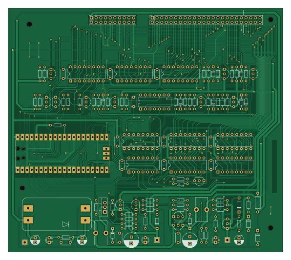
USB Flash/EPROM Programmer is an open source RP2040/RP2350 PCB design by robsonsmartins, published on GitHub under the CC-BY-NC-4.0 license. It is a 2-layer board measuring 148.8 × 132.2 mm, with 121 components from 38 distinct parts.
Its main chip is the Pico, from the RP2040/RP2350 family. Other key parts include the MT3608 Module, 74LS06N, 74HC595 and 74HC165. By type, the board carries 52 resistors, 18 capacitors, 16 transistors, 16 diodes, 12 ICs and 3 test points.
It belongs with the usb & debug tools designs in this gallery.
From the project
A memory device programmer (Flash/EPROM/E2PROM) board and software, connected to PC by USB port.
A memory device programmer (Flash/EPROM/E2PROM) board and software, connected to PC by USB port.
The most up-to-date schematic diagram can be accessed here: Schematic diagram of the USB Flash/EPROM Programmer.
The most up-to-date BOM can be accessed here: Bill of Materials of the USB Flash/EPROM Programmer.
The following CAD software (opensource and multiplatform) was used to draw the schematic diagram and PCB:

Main components on the USB Flash/EPROM Programmer
USB Flash/EPROM Programmer bill of materials (BOM)
121 components, 38 distinct parts — part numbers from the project's BOM.
| Qty | Part | Footprint | Refs |
|---|---|---|---|
| 1 | MT3608 Module | MT3608_module | U1 |
| 2 | 74LS06N | DIP-14_W7.62mm | U2, U8 |
| 1 | Pico | RPi_Pico_SMD_TH | U3 |
| 6 | 74HC595 | DIP-16_W7.62mm | U4, U5, U6, U7, U9, U10 |
| 2 | 74HC165 | DIP-16_W7.62mm | U11, U12 |
| 6 | BC547 | TO-92_Inline_Wide | Q1, Q12, Q13, Q14, Q15, Q16 |
| 4 | BC327 | TO-92_Inline_Wide | Q2, Q3, Q4, Q6 |
| 1 | TIP120 | TO-220-3_Vertical | Q5 |
| 5 | BC557 | TO-92_Inline_Wide | Q7, Q8, Q9, Q10, Q11 |
| 1 | Parallel Adapter | PinSocket_2x24_P2.54mm_Vertical | J2 |
| 1 | Serial Adapter | PinSocket_2x10_P2.54mm_Vertical | J3 |
| 1 | VDD | TestPoint_THTPad_2.5x2.5mm_Drill1.2mm | TP1 |
| 1 | GND | TestPoint_THTPad_2.5x2.5mm_Drill1.2mm | TP2 |
| 1 | VPP | TestPoint_THTPad_2.5x2.5mm_Drill1.2mm | TP3 |
| 1 | GREEN | LED_D3.0mm | D3 |
| 1 | RED | LED_D3.0mm | D6 |
| 2 | BAT46 | D_DO-34_SOD68_P7.62mm_Horizontal | D7, D11 |
| 2 | 1N4733A | D_DO-35_SOD27_P7.62mm_Horizontal | D8, D19 |
| 8 | 1N4148 | D_DO-34_SOD68_P7.62mm_Horizontal | D9, D12, D13, D14, D15, D16, D17, D18 |
| 1 | YELLOW | LED_D3.0mm | D10 |
Show 18 more
| Qty | Part | Footprint | Refs |
|---|---|---|---|
| 1 | 1N4743A | D_DO-35_SOD27_P7.62mm_Horizontal | D20 |
| 1 | 100uH | L_Toroid_Vertical_L13.0mm_W6.5mm_P5.60mm | L1 |
| 1 | 300uH | L_Toroid_Vertical_L13.0mm_W6.5mm_P5.60mm | L2 |
| 2 | 10uF | CP_Radial_D5.0mm_P2.50mm | C1, C2 |
| 13 | 100nF | C_Disc_D5.0mm_W2.5mm_P5.00mm | C3, C5, C7, C9, C10, C11, C12, C13 +5 |
| 1 | 470uF | CP_Radial_D8.0mm_P3.80mm | C4 |
| 1 | 22uF | CP_Radial_D5.0mm_P2.50mm | C6 |
| 1 | 100uF | CP_Radial_D8.0mm_P3.50mm | C8 |
| 19 | 2K2 | R_Axial_DIN0204_L3.6mm_D1.6mm_P7.62mm_Horizontal | R1, R5, R6, R7, R12, R13, R18, R25 +11 |
| 5 | 100R | R_Axial_DIN0204_L3.6mm_D1.6mm_P7.62mm_Horizontal | R2, R11, R15, R40, R51 |
| 7 | 1K | R_Axial_DIN0204_L3.6mm_D1.6mm_P7.62mm_Horizontal | R3, R8, R22, R43, R45, R47, R48 |
| 10 | 4K7 | R_Axial_DIN0204_L3.6mm_D1.6mm_P7.62mm_Horizontal | R4, R17, R19, R23, R24, R29, R30, R31 +2 |
| 5 | 470R | R_Axial_DIN0204_L3.6mm_D1.6mm_P7.62mm_Horizontal | R9, R21, R34, R36, R41 |
| 1 | 330R | R_Axial_DIN0204_L3.6mm_D1.6mm_P7.62mm_Horizontal | R10 |
| 2 | 10K | R_Axial_DIN0204_L3.6mm_D1.6mm_P7.62mm_Horizontal | R14, R32 |
| 1 | 220R | R_Axial_DIN0204_L3.6mm_D1.6mm_P7.62mm_Horizontal | R16 |
| 1 | 3K9 | R_Axial_DIN0204_L3.6mm_D1.6mm_P7.62mm_Horizontal | R20 |
| 1 | 560R | R_Axial_DIN0207_L6.3mm_D2.5mm_P10.16mm_Horizontal | R52 |
USB Flash/EPROM Programmer design files
The KiCad project lives in the robsonsmartins/usbflashprog repository on GitHub; these links point at the commit this page was built from.
USB Flash/EPROM Programmer: common questions
What microcontroller does the USB Flash/EPROM Programmer use?
The USB Flash/EPROM Programmer is built around the Pico, from the RP2040/RP2350 family.
How big is the USB Flash/EPROM Programmer PCB?
The USB Flash/EPROM Programmer measures 148.8 × 132.2 mm, has 2 copper layers and is 1.6 mm thick.
How many components are on the USB Flash/EPROM Programmer?
121 components, from 38 distinct parts, with part numbers taken from the project's own BOM. The full bill of materials is listed on this page.
Where can I download the USB Flash/EPROM Programmer design files?
From the robsonsmartins/usbflashprog repository on GitHub, which has the KiCad layout, the schematic and the BOM; the links under Design files point to each one.
Can I use the USB Flash/EPROM Programmer design in my own project?
It is published under CC-BY-NC-4.0, which limits how it may be reused; read the license before building on it.
Can I test firmware for the USB Flash/EPROM Programmer without the hardware?
Yes. HardLabs builds a simulation of the board from its netlist and BOM, so you can run and debug RP2040/RP2350 firmware against it before you order a PCB.
More boards in usbflashprog
Similar boards
 RP2040/RP2350
Open Book Abridged Edition
joeycastillo
85 × 115 mm29 parts2LCC-BY-SA-4.08.1k RP2040/RP2350
Corne
foostan
277.2 × 107.5 mm164 parts2LCC-BY-4.07.7k RP2040/RP2350
Corne
277.2 × 107.5 mm164 parts2LCC-BY-4.07.7k RP2040/RP2350
LogicAnalyzer
gusmanb
57 × 55.2 mm6 parts2LGPL-3.05.0k RP2040/RP2350
Jitx design
55.5 × 65 mm26 parts4LGPL-3.05.0k RP2040/RP2350
Pro V2
kata0510
290.1 × 130 mm270 parts2LMIT2.3k