
Tempo bt

About the Tempo bt PCB
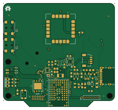
Tempo bt is an open source Microchip SAM PCB design by rrainey, published on GitHub under the GPL-3.0 license. It is a 4-layer board measuring 58.4 × 54 mm, with 59 components from 45 distinct parts.
Its main chip is the DMP3125L-7, from the Microchip SAM family. Other key parts include the BMP390, SAM-M10Q-00B, MMC5983MA, ICM-42688-V and UBXH13-0000138. By type, the board carries 16 resistors, 14 capacitors, 8 ICs, 4 connectors, 4 switches and 4 LEDs.
From the project
Audible information for skydivers
Core MCU/Module: u‑blox NORA‑B106 (nRF5340) OS: Zephyr RTOS Goal: Provide a canonical, test‑ready mapping of logical nets from the NORA‑B106 to each peripheral IC for driver bring‑up and HW connectivity tests.
Additional compatibility labels seen on sheet:
FLASHMOSI, FLASHMISO, FLASHSCK appear alongside the QSPI set; treat as alternative/legacy SPI naming used at fan‑out or test points.
Main components on the Tempo bt
Tempo bt bill of materials (BOM)
59 components, 45 distinct parts — part numbers from the project's BOM.
| Qty | Part | Footprint | Refs |
|---|---|---|---|
| 1 | BMP390 | LGA10_BMP390_BOS | U1 |
| 1 | SAM-M10Q-00B SAM-M10Q | MODULE_SAM-M8Q-0-10 | U2 |
| 1 | MMC5983MA | MMC5983MA_MEM | U3 |
| 1 | ICM-42688-V | PQFN50P300X250X97-14N | U4 |
| 1 | UBXH13-0000138 MX25R64 | WSON-8-1EP_6x5mm_P1.27mm_EP3.4x4mm | U5 |
| 1 | SPX3819M5-L-3-3/TR | SOT23-5 | U6 |
| 1 | NORA-B106-00B | XCVR_NORA-B106-00B | U7 |
| 1 | MCP73831T-4ADI/OT MCP73831 | SOT23-5 | U8 |
| 1 | DMP3125L-7 | SOT23-3@1 | Q1 |
| 1 | MEM2061-01-188-00-A | MICROSD | X1 |
| 1 | ABS07-120-32.768KHZ-T 32.768kHz | CRYSTAL-SMD-3.2X1.5MM | Y1 |
| 1 | S2B-PH-SM4-TB JSTPH | JSTPH2 | J1 |
| 1 | USB4105-GF-A-120 USB_C_Receptacle_USB2.0 | GCT-USB4105-GF-A modified-USB-C 16P | J2 |
| 1 | SM04B-SRSS-TB QWIIC_CONNECTORJS-1MM | JST04_1MM_RA | J4 |
| 1 | M50-3500542 2x5 PTH ARM CORTEX DEBUG | 2X5-PTH-1.27MM-NO_SILK | J5 |
| 1 | 1056TR CR1220 | CR1220-2 | B1 |
| 1 | SMD0805B050TF 500mA, 6V | Fuse_0805_2012Metric | F1 |
| 1 | UBXH11-0000058 LTST-C19HE1WT | LTST-C19HE1WT | RGB1 |
| 1 | JS102011SAQN | JS102011SAQN | SW1 |
| 2 | UBXH19-0000035 PTS850 | PTS850-with-bosses | SW2, SW3 |
Show 25 more
| Qty | Part | Footprint | Refs |
|---|---|---|---|
| 1 | KMR221NG LFS RESET | SW_Push_1P1T_NO_CK_KMR2 | SW4 |
| 2 | LTST-S270KGKT | LED_0603_1608Metric | LED1, LED3 |
| 1 | LTST-S270KRKT | LED_0603_1608Metric | LED2 |
| 1 | LTST-S270YKT Yellow | LED-0603 | LED4 |
| 2 | UBXH07-0000034 | D_SOD-923 | D1, D2 |
| 1 | BAT20JFILM 1A/23V/620mV | SOD-323 | D5 |
| 2 | VJ0603Y104KCXAT 100nF | C_0603_1608Metric | C1, C3 |
| 3 | GRM188Z71A106MA73J 10uF | C_0603_1608Metric | C2, C4, C8 |
| 1 | GRT033C81A104KE01D 0.1uF | C_0603_1608Metric | C5 |
| 1 | CGA3E2X7R1H103K080AE 10nF | C_0603_1608Metric | C6 |
| 1 | GRM188R71A225KE15D 2.2uF | C_0603_1608Metric | C7 |
| 1 | UBXH01-2021002 100nF | C_0402_1005Metric | C9 |
| 1 | 0603DC105KAT2A 1.0UF-0603-16V-10%-X7R | C_0603_1608Metric | C10 |
| 1 | GRM188Z71C225KE43D 2.2UF-0603-10V-20% | C_0603_1608Metric | C11 |
| 2 | GRM188Z71A475KE15D 4.7UF-0603-6.3V-(10%) | C_0603_1608Metric | C12, C15 |
| 1 | GRM21BR71A475KE51L 4.7UF-0805-10V-10% | 0805 | C13 |
| 2 | RCC04025K10FKED 5.1k | R_0402_1005Metric | R1, R2 |
| 2 | ERJ-H3EF2201V 2.2KOHM-0603-1/10W-1% | 0603 | R3, R4 |
| 3 | ERJ-H3EF2201V 2.2K | R_0603_1608Metric | R5, R9, R10 |
| 1 | UBXH18-0000269 499OHM-0402 | R_0402_1005Metric | R6 |
| 2 | UBXH18-0008033 220OHM-0402 | R_0402_1005Metric | R7, R8 |
| 3 | ERJ-H3EF1002V 10KOHM-0603-1/10W-1% | 0603 | R11, R13, R14 |
| 1 | UBXH18-0008113 470KOHM | R_0402_1005Metric | R12 |
| 1 | MR06X1001FTL 1K | 0603 | R15 |
| 1 | MR06X2001FTL 2.0k | 0603 | R16 |
Tempo bt design files
The KiCad project lives in the rrainey/tempo repository on GitHub; these links point at the commit this page was built from.
Tempo bt: common questions
What microcontroller does the Tempo bt use?
The Tempo bt is built around the DMP3125L-7, from the Microchip SAM family.
How big is the Tempo bt PCB?
The Tempo bt measures 58.4 × 54 mm, has 4 copper layers and is 1.6 mm thick.
How many components are on the Tempo bt?
59 components, from 45 distinct parts, with part numbers taken from the project's own BOM. The full bill of materials is listed on this page.
Where can I download the Tempo bt design files?
From the rrainey/tempo repository on GitHub, which has the KiCad layout, the schematic and the BOM; the links under Design files point to each one.
Can I use the Tempo bt design in my own project?
Yes, under the terms of its GPL-3.0 license, which rrainey chose for the repository.
Can I test firmware for the Tempo bt without the hardware?
Yes. HardLabs builds a simulation of the board from its netlist and BOM, so you can run and debug Microchip SAM firmware against it before you order a PCB.
More boards in tempo
Similar boards
 Microchip SAM
Fpgaboy
Wren6991
50 × 50 mm89 parts4LNo license508 Microchip SAM
Kira
kiibohd
366.9 × 114.3 mm400 partsCERN-OHL-1.2415 Microchip SAM
DSKY driver
benkrasnow
43 × 92.3 mm44 partsMIT258 Microchip SAM
Duet 2 Maestro
Duet3D
100 × 123 mm336 partsCERN-OHL-1.2257 Microchip SAM
Makennbot
idlehandsdev
60 × 75 mm53 parts2LNo license175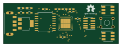 Microchip SAM
Oxidized flash
blakesmith
61 × 21.6 mm19 parts2LNo license167