
Finger FSR V1 main

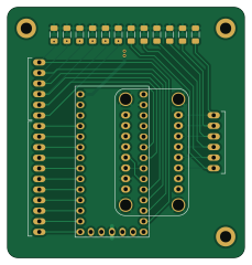
About the Finger FSR V1 main PCB
Finger FSR V1 main is an open source NXP PCB design by selina101, published on GitHub. It is a 2-layer board measuring 57 × 60 mm, with 37 components from 4 distinct parts.
Its main chip is the Teensy_4.0, from the NXP family. By type, the board carries 23 connectors, 12 resistors and 2 ICs.
From the project
Repo with projects done during my thesis and the valorisation.
There are three PCBs for the finger FSRs: - The FPCB that has the electrodes in its height. It has the back side in contact with the finger, and the electrodes in contact with the velostat. - The FPCB that has the electrodes in its width, and the circular electrodes on the front. The rectangular electrodes are put in contact with the velostat, and the circular electrodes allow for connections to a hydrogel if desired - A main PCB that helps connect all these electrodes to a Teensy microcontroller.
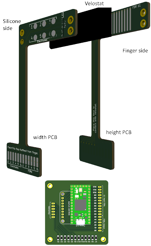
Main components on the Finger FSR V1 main
Finger FSR V1 main bill of materials (BOM)
37 components, 4 distinct parts — part numbers from the project's BOM.
| Qty | Part | Footprint | Refs |
|---|---|---|---|
| 1 | ~ | Adafruit_ADS7830_Breakout | IC1 |
| 1 | Teensy_4.0 | Teensy_4.0 | U1 |
| 23 | ~ | TH_Pad | J1, J2, J3, J4, J5, J6, J7, J8 +15 |
| 12 | R | R_1206_3216Metric_Pad1.30x1.75mm_HandSolder | R1, R2, R3, R4, R5, R6, R7, R8 +4 |
Finger FSR V1 main design files
The KiCad project lives in the selina101/CreateLabWork repository on GitHub; these links point at the commit this page was built from.
Finger FSR V1 main: common questions
What microcontroller does the Finger FSR V1 main use?
The Finger FSR V1 main is built around the Teensy_4.0, from the NXP family.
How big is the Finger FSR V1 main PCB?
The Finger FSR V1 main measures 57 × 60 mm, has 2 copper layers and is 1.6 mm thick.
How many components are on the Finger FSR V1 main?
37 components, from 4 distinct parts, with part numbers taken from the project's own BOM. The full bill of materials is listed on this page.
Where can I download the Finger FSR V1 main design files?
From the selina101/CreateLabWork repository on GitHub, which has the KiCad layout, the schematic and the BOM; the links under Design files point to each one.
Can I use the Finger FSR V1 main design in my own project?
The repository has no license, so all rights stay with selina101. Use it as a reference, and ask the author before reusing the design.
Can I test firmware for the Finger FSR V1 main without the hardware?
Yes. HardLabs builds a simulation of the board from its netlist and BOM, so you can run and debug NXP firmware against it before you order a PCB.
More boards in CreateLabWork
 NXP
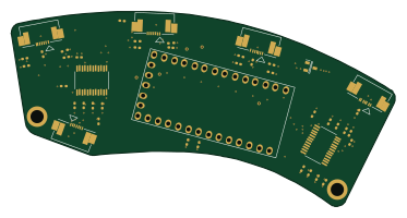
MainPCB V3
93.1 × 47.3 mm72 parts4LNo license0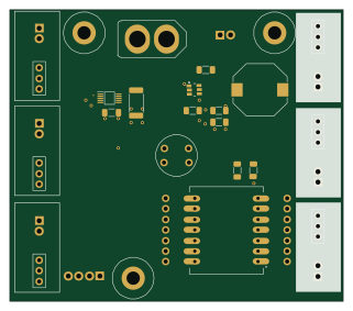 ESP32
Max Main
80 × 70 mm29 parts4LNo license0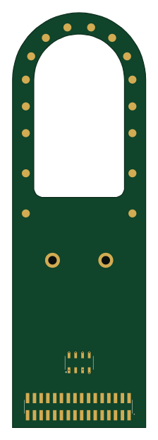
Benhui Tongue
50 × 155 mm28 parts2LNo license0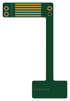
Finger FSR V1 length
55.3 × 82.3 mm24 parts2LNo license0
Index Middle Ring V3
188.9 × 26.5 mm15 parts2LNo license0
IMU6
10 × 10 mm15 parts2LNo license0
IMU V3
10 × 12 mm12 parts4LNo license0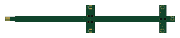
Pinky V1
157.3 × 26.5 mm11 parts2LNo license0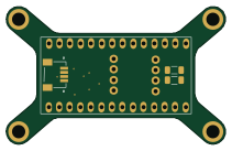 NXP
IMU Main
52.8 × 33 mm9 parts2LNo license0
Thumb V1
240.6 × 26.5 mm7 parts2LNo license0
Similar boards
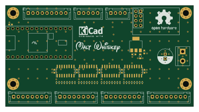 NXP
32Bit shift register
MaltWhiskey
100 × 54 mm56 parts4LNo license763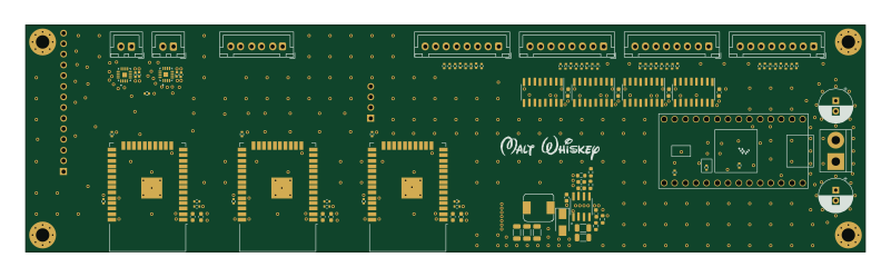 NXP
Mega-Cube-Board
200 × 54 mm100 parts4LNo license763 NXP
MCL6809
MicroCoreLabs
32.3 × 61 mm7 parts4LNo license532 NXP
MCL68
31.6 × 84.1 mm13 parts4LNo license532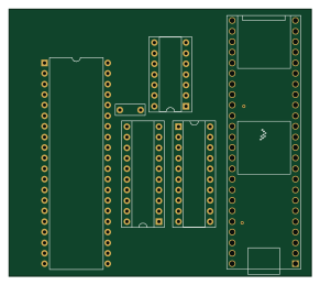 NXP
MCL65+
72.6 × 64.1 mm6 parts2LNo license532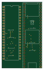 NXP
MCLZ8
37.1 × 61.5 mm6 parts4LNo license532