
Esp8266 test board

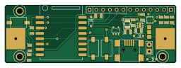
About the Esp8266 test board
Esp8266 test board is an open source PCB design by sifourquier, published on GitHub. It is a 2-layer board measuring 64 × 21.5 mm, with 31 components from 23 distinct parts.
Other key parts include the TPS61291, BME, ESP-07V2 and LP2985_D3.3. By type, the board carries 8 connectors, 7 capacitors, 4 ICs, 4 resistors, 3 switches and 3 diodes.
It belongs with the sensors designs in this gallery.
From the project
hardware for a system based on esp8266
Electronic for meteo sensors (Temperature Humidity Pressure) Power by 1 or 2 battery 1.2V/1.5V or 5V (mini USB) 1 batterie R14 can spupply for more of 6 months if configured on static ip
FIXME If use with only 1battery the stepup are to low current i have fix it by using 0x220uF on the power but work only if the connection time are low (use IP fix do not use dhcp) If you use a rechargabel battery you can chage with connecting to usb but the heating of charge distorts the measure
Main components on the Esp8266 test board
Esp8266 test board bill of materials (BOM)
31 components, 23 distinct parts.
| Qty | Part | Footprint | Refs |
|---|---|---|---|
| 1 | TPS61291 | PWSON-N6 | U1 |
| 1 | BME | LGA8_2.5×2.5 | U2 |
| 1 | ESP-07V2 | ESP-07v2 | U3 |
| 1 | LP2985_D3.3 | SOT23-5 | U4 |
| 1 | USB-MINI-B-SMD | USB_MINI_B | J1 |
| 1 | Solar | SIL-2 | P1 |
| 1 | CONN_6 | SIL-6 | P2 |
| 1 | CONN_7 | SIL-7 | P3 |
| 1 | NIMH 1.2V | AA | P8 |
| 3 | DRILL | 1pin | P9, P10, P12 |
| 1 | CONN_3 | JUMP-3 | K1 |
| 1 | RST | SW_PUSH_SMD_2pad | SW1 |
| 1 | BOOT | SW_PUSH_SMD_2pad | SW2 |
| 1 | PUSH | SW_PUSH_SMD_2pad | SW3 |
| 2 | SD103 | SOD123_Corige | D1, D3 |
| 1 | 1n4148 | SOD123_Corige | D2 |
| 1 | 3.3uH | ipc-7351-inductor-INDC2520X220N | L1 |
| 3 | 22uF | SM0805 | C1, C2, C5 |
| 3 | 100nF | SM0805 | C3, C4, C6 |
| 1 | C | SM0805 | C7 |
Show 3 more
| Qty | Part | Footprint | Refs |
|---|---|---|---|
| 1 | 10 | SM0805 | R1 |
| 1 | 1k | SM0805 | R2 |
| 2 | 2.2M | SM0805 | R3, R4 |
Esp8266 test board design files
The KiCad project lives in the sifourquier/domotic_esp_hardware repository on GitHub; these links point at the commit this page was built from.
Esp8266 test board: common questions
How big is the Esp8266 test board?
The Esp8266 test board measures 64 × 21.5 mm, has 2 copper layers and is 1.6 mm thick.
How many components are on the Esp8266 test board?
31 components, from 23 distinct parts. The full bill of materials is listed on this page.
Where can I download the Esp8266 test board design files?
From the sifourquier/domotic_esp_hardware repository on GitHub, which has the KiCad layout; the links under Design files point to each one.
Can I use the Esp8266 test board design in my own project?
The repository has no license, so all rights stay with sifourquier. Use it as a reference, and ask the author before reusing the design.
More boards in domotic_esp_hardware
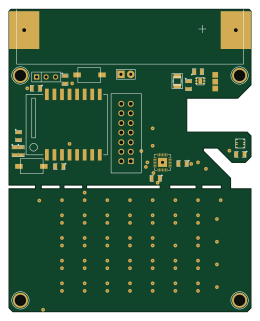
Esp8266 test board (Copie en conflit de Steven 2015-08-28)
64 × 80 mm120 parts2LNo license0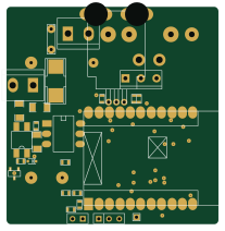 ESP8266
Esp8266 test board (Copie en conflit de Simon Fourquier 2015-04-21)
51.7 × 52.9 mm55 parts2LNo license0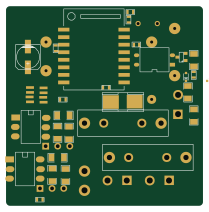
.kicad
52.2 × 52.9 mm51 parts2LNo license0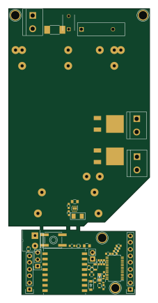
Button
53.5 × 108.5 mm49 parts2LNo license0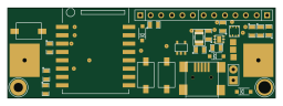
Esp8266 test board (Copie en conflit de Simon Fourquier 2015-08-26)
64 × 21.5 mm32 parts2LNo license0
Similar boards
Sensor smd
scottbez1
40 × 20 mm5 parts2LApache-2.04.2k
Sensors
StuckAtPrototype
15.2 × 9 mm14 parts4LApache-2.03.8k
Microphone
Mentra-Community
5.5 × 6.1 mm6 parts2LMIT1.2k
TemperaturePCB PANEL
stuartpittaway
116 × 75.5 mm178 parts2LCC-BY-NC-4.01.1k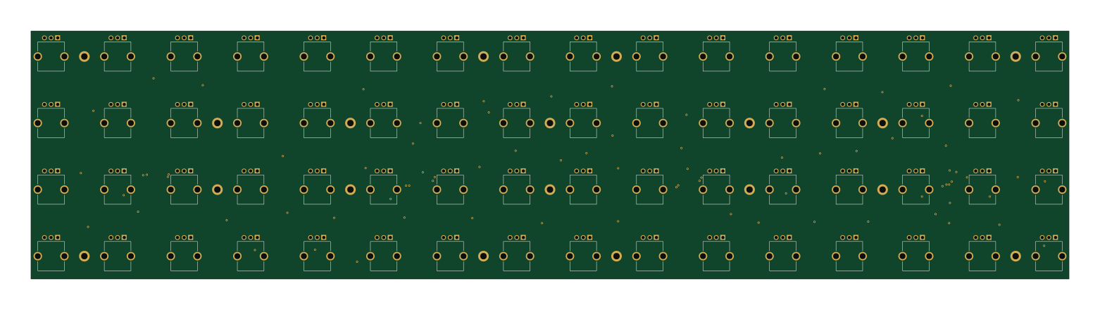
Pots
shanteacontrols
390 × 93 mm75 parts2LApache-2.0956
USB
52 × 12.6 mm6 parts2LApache-2.0956