
Soldered-Inkplate-2-hardware design

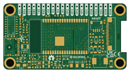
About the Soldered-Inkplate-2-hardware design PCB
Soldered-Inkplate-2-hardware design is an open source ESP32 PCB design by SolderedElectronics, published on GitHub under the TAPR-OHL-1.0 license. It is a 4-layer board measuring 65.2 × 35.2 mm, with 97 components from 36 distinct parts.
Its main chip is the ESP32-WROVER-IE-N4R8, from the ESP32 family. Other key parts include the CH340C, MCP73831T-2ATI/OT, TPS7A2633DRVR, GDEH0213Z19 and TPS3840PL27DBVR. By type, the board carries 25 capacitors, 24 relays, 21 resistors, 6 ICs, 5 diodes and 4 transistors.
It belongs with the iot & wireless and displays & leds designs in this gallery.
From the project
Hardware design, BOM, gerbers, 3D files and pinout for Soldered-Inkplate-2 designed by Soldered Electronics.
The Inkplate 2 is an Arduino-compatible board that features a 2.13" three-color e-paper display. It is a plug-and-play device, programmable via USB port, and controlled by an ESP32 microcontroller. Moreover, it connects to the internet via WiFi or Bluetooth. Since it uses only 8uA in low-power mode, it can last for months on a single Li-ion battery charge. It's simple enough to be used by beginners, but it also offers plenty of features and a user-friendly platform for advanced users. Inkplate 2 has it all, packed on a small-factor board.

Main components on the Soldered-Inkplate-2-hardware design
Soldered-Inkplate-2-hardware design bill of materials (BOM)
97 components, 36 distinct parts — part numbers from the project's BOM.
| Qty | Part | Footprint | Refs |
|---|---|---|---|
| 1 | ESP32-WROVER-IE-N4R8 | ESP32-WROVER | U1 |
| 1 | CH340C | SOP-16 | U2 |
| 1 | MCP73831T-2ATI/OT | SOT-23-5 | U3 |
| 1 | TPS7A2633DRVR | TPS7A2633DRVR | U4 |
| 1 | GDEH0213Z19 | GDEH0213Z19 | U5 |
| 1 | TPS3840PL27DBVR | SOT-23-5 | U6 |
| 1 | SSM3J358R,LF | SOT-23-3 | Q1 |
| 2 | NPN | SOT-23-3 | Q2, Q3 |
| 1 | CJ2310 | SOT-23-3 | Q7 |
| 1 | 1206FUSE_500mA | 1206FUSE | F1 |
| 4 | Standoff_M3 | Standoff_M3 | H1, H2, H3, H4 |
| 20 | HEADER_MALE_1X1_Inkplate | HEADER_MALE_1X1_Inkplate | K1, K3, K4, K5, K6, K7, K8, K9 +12 |
| 1 | easyC-SMD | easyC-connector | K2 |
| 1 | TX2400-FPC-5015 | TX2400-FPC-5015 | K19 |
| 1 | U262-161N-4BVC11 | U262-161N-4BVC11 | K20 |
| 1 | SFV24R-1STBE1HLF | SFV24R-2STBE1HLF | K24 |
| 5 | PAD_2x1.5 | PAD_2x1.5 | PAD1, PAD2, PAD3, PAD4, PAD5 |
| 1 | YTSA007A0151803B | YTSA007A0151803B | SW1 |
| 1 | RED | 0402LED | D1 |
| 1 | BAT20J | SOD-323 | D2 |
Show 16 more
| Qty | Part | Footprint | Refs |
|---|---|---|---|
| 3 | MBR0530T1G | SOD-123 | D4, D5, D6 |
| 1 | PSPMAA0603-100M-ANF | Inductor_SMD_7x6.6 | L1 |
| 3 | 10u | 1206C | C1, C8, C11 |
| 5 | 2u2 | 0603C | C2, C4, C7, C9, C13 |
| 6 | 100n | 0603C | C3, C5, C6, C10, C12, C26 |
| 9 | C1608X5R1H105K080AB | 0603C | C14, C15, C16, C17, C18, C19, C20, C21 +1 |
| 2 | CL31B475KBHNFNE | 1206C | C22, C23 |
| 4 | 10k | 0603R | R1, R2, R12, R13 |
| 8 | 100k | 0603R | R3, R11, R14, R15, R16, R17, R18, R19 |
| 1 | 47R | 0603R | R4 |
| 1 | 2k2 | 0402R | R5 |
| 2 | 5k1 | 0603R | R6, R7 |
| 2 | 1k | 0603R | R8, R9 |
| 1 | 2k49 | 0603R | R10 |
| 1 | 1M | 0603R | R21 |
| 1 | 0603WAF470LT5E | 0603R | R22 |
Soldered-Inkplate-2-hardware design design files
The KiCad project lives in the SolderedElectronics/Soldered-Inkplate-2-hardware-design repository on GitHub; these links point at the commit this page was built from.
Soldered-Inkplate-2-hardware design: common questions
What microcontroller does the Soldered-Inkplate-2-hardware design use?
The Soldered-Inkplate-2-hardware design is built around the ESP32-WROVER-IE-N4R8, from the ESP32 family.
How big is the Soldered-Inkplate-2-hardware design PCB?
The Soldered-Inkplate-2-hardware design measures 65.2 × 35.2 mm, has 4 copper layers and is 1.6 mm thick.
How many components are on the Soldered-Inkplate-2-hardware design?
97 components, from 36 distinct parts, with part numbers taken from the project's own BOM. The full bill of materials is listed on this page.
Where can I download the Soldered-Inkplate-2-hardware design design files?
From the SolderedElectronics/Soldered-Inkplate-2-hardware-design repository on GitHub, which has the KiCad layout, the schematic and the BOM; the links under Design files point to each one.
Can I use the Soldered-Inkplate-2-hardware design design in my own project?
Yes, under the terms of its TAPR-OHL-1.0 license, which SolderedElectronics chose for the repository.
Can I test firmware for the Soldered-Inkplate-2-hardware design without the hardware?
Yes. HardLabs builds a simulation of the board from its netlist and BOM, so you can run and debug ESP32 firmware against it before you order a PCB.
Similar boards
 ESP32
ESP32Open Book Abridged Edition
joeycastillo
85 × 115 mm65 parts2LCC-BY-SA-4.08.1k ESP32
ESP32Esp32 minimal
atopile
36.2 × 26.8 mm20 parts2LMIT4.0k ESP32
ESP32Badge
56.3 × 39 mm239 parts4LMIT4.0k ESP32
ESP32Controller
StuckAtPrototype
29 × 74 mm58 parts4LApache-2.03.8k ESP32
ESP32Racer
36 × 50.2 mm70 parts4LApache-2.03.8k ESP32
ESP32Bitaxe
skot
56.5 × 99.8 mm86 parts4LCERN-OHL-S-2.01.4k