
Microver2026 Modular Final

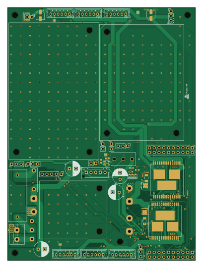
About the Microver2026 Modular Final PCB
Microver2026 Modular Final is an open source PCB design by Tim4769, published on GitHub under the Custom license license. It is a 4-layer board measuring 100 × 135 mm, with 47 components from 39 distinct parts.
Other key parts include the C2653552, C840100 and C626098. By type, the board carries 23 connectors, 10 capacitors, 5 ICs, 3 diodes, 3 resistors and 2 switches.
It belongs with the robotics & motion designs in this gallery.
From the project
Swiss Rover Challenge rover project with final electronics, mechanical handoff files, PCB validation firmware, and shared project assets.
Revision: Rev B Production status: Not produced / not fabricated Project: Project CK
The main correction in this KiCad project is that the second motor-driver output net issue from Rev A has been resolved: the connection intended for OUTA is no longer tied to the OUTB net.
Do not fabricate or use this design as-is for a 36 V boosted motor rail. If this design is used as the starting point for a future control board, the motor-driver stage should be redesigned with a driver/controller that is suitable for the intended boosted motor voltage. Possible examples include:

Main components on the Microver2026 Modular Final
Microver2026 Modular Final bill of materials (BOM)
47 components, 39 distinct parts — part numbers from the project's BOM.
| Qty | Part | Footprint | Refs |
|---|---|---|---|
| 2 | C2653552 VNH5019A-E | SOIC_5019A-E_STM | U1, U2 |
| 2 | C840100 CSD18543Q3A | DNH0008A | U3, U4 |
| 1 | C626098 MIC5365-3.3YD5 | SOT-23-5 | U5 |
| 1 | C2937625 Fan control | PinHeader_1x03_P2.54mm_Vertical | J1 |
| 1 | C492401 PGD_Prot | PinHeader_1x02_P2.54mm_Vertical | J2 |
| 1 | C492401 on/off_Boost | PinHeader_1x02_P2.54mm_Vertical | J3 |
| 1 | DRIVE_1 Drive_1 | JST_PH_B6B-PH-K_1x06_P2.00mm_Vertical | J10 |
| 1 | DRIVE_2 Drive_2 | JST_PH_B6B-PH-K_1x06_P2.00mm_Vertical | J11 |
| 1 | DRIVE_3 Drive_3 | JST_PH_B6B-PH-K_1x06_P2.00mm_Vertical | J12 |
| 1 | DRIVE_4 Drive_4 | JST_PH_B6B-PH-K_1x06_P2.00mm_Vertical | J13 |
| 1 | C492427 Left | PinHeader_2x10_P2.54mm_Vertical | J14 |
| 1 | C492427 Right | PinHeader_2x10_P2.54mm_Vertical | J15 |
| 1 | DRIVE_5 Drive_5 | JST_PH_B6B-PH-K_1x06_P2.00mm_Vertical | J16 |
| 1 | DRIVE_6 Drive_6 | JST_PH_B6B-PH-K_1x06_P2.00mm_Vertical | J17 |
| 1 | Lidar pins | JST_XH_B5B-XH-AM_1x05_P2.50mm_Vertical | J18 |
| 1 | C8269 VIN_5V | SolderWire-0.75sqmm_1x02_P7mm_D1.25mm_OD3.5mm | J19 |
| 1 | C492404 Spare pins | PinHeader_1x05_P2.54mm_Vertical | J20 |
| 1 | C2937625 Servo 1 | PinHeader_1x03_P2.54mm_Vertical | J24 |
| 1 | C2937625 Servo 2 | PinHeader_1x03_P2.54mm_Vertical | J25 |
| 1 | C2937625 Servo 3 | PinHeader_1x03_P2.54mm_Vertical | J26 |
Show 19 more
| Qty | Part | Footprint | Refs |
|---|---|---|---|
| 1 | C2937625 Servo 4 | PinHeader_1x03_P2.54mm_Vertical | J27 |
| 1 | C8269 VOUT_Higher | SolderWire-0.75sqmm_1x02_P7mm_D1.25mm_OD3.5mm | J28 |
| 1 | C492401 Pi 5 TX and RX UART0 (PL011) | PinHeader_1x02_P2.54mm_Vertical | J29 |
| 1 | C492401 Pi power pins | PinHeader_1x02_P2.54mm_Vertical | J30 |
| 1 | C8269 VIN_Pre | TerminalBlock_MaiXu_MX126-5.0-02P_1x02_P5.00mm | J31 |
| 1 | C8269 VOUT_Pre | SolderWire-0.75sqmm_1x02_P7mm_D1.25mm_OD3.5mm | J32 |
| 1 | C717030 Fuse | Fuse PTF-77 | F1 |
| 1 | C319012 1MS1T1B1M2QES | SS-12D10G5_XKB | SW1 |
| 1 | SW_SPDT | SolderWire-0.5sqmm_1x03_P4.8mm_D0.9mm_OD2.3mm | SW2 |
| 1 | C126319 3.3V | LED_0603_1608Metric | D1 |
| 1 | C22371297 5V | LED_0603_1608Metric | D2 |
| 1 | C22371297 18V | LED_0603_1608Metric | D3 |
| 4 | C106697 220uF | CP_Radial_D8.0mm_P3.50mm | C1, C3, C7, C16 |
| 2 | C19666 4.7uF | C_0603_1608Metric | C2, C6 |
| 2 | C29823 4.7 uF | C_1206_3216Metric | C4, C5 |
| 2 | C116389 220 uF | CP_Elec_4x5.4 | C8, C9 |
| 1 | C23138 330Ω | R_0603_1608Metric | R1 |
| 1 | C22765 1.2kΩ | R_0603_1608Metric | R2 |
| 1 | C23212 6.8kΩ | R_0603_1608Metric | R3 |
Microver2026 Modular Final design files
The KiCad project lives in the Tim4769/Microver repository on GitHub; these links point at the commit this page was built from.
- Layouthardware/final/(not produced) final_control_board_rev_b/Kicad_Microver2026_Modular_Final/Microver2026_Modular_Final.kicad_pcb
- Schematichardware/final/(not produced) final_control_board_rev_b/Kicad_Microver2026_Modular_Final/Microver2026_Modular_Final.kicad_sch
- BOMhardware/final/final_control_board_rev_a/BOM.csv
Microver2026 Modular Final: common questions
How big is the Microver2026 Modular Final PCB?
The Microver2026 Modular Final measures 100 × 135 mm, has 4 copper layers and is 1.599 mm thick.
How many components are on the Microver2026 Modular Final?
47 components, from 39 distinct parts, with part numbers taken from the project's own BOM. The full bill of materials is listed on this page.
Where can I download the Microver2026 Modular Final design files?
From the Tim4769/Microver repository on GitHub, which has the KiCad layout, the schematic and the BOM; the links under Design files point to each one.
Can I use the Microver2026 Modular Final design in my own project?
It is published under Custom license, which limits how it may be reused; read the license before building on it.
More boards in Microver
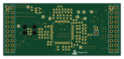 STM32
Compute unit STM32G4RCT6
63 × 28 mm54 parts4LCustom license0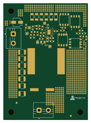
18V to 5V 15A buck converter
45 × 62 mm49 parts4LCustom license0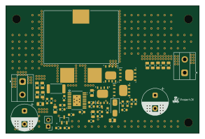
15-22V to 36V Boost converter
73 × 48 mm49 parts4LCustom license0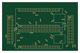 AVR/Arduino
Arduinos Compute Unit
70 × 45 mm37 parts4LCustom license0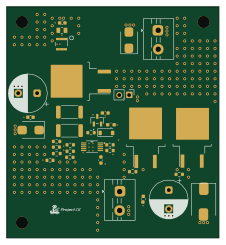
Reverse and surge current protection
56 × 61 mm36 parts4LCustom license0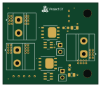 NXP
High side or ing power selection
36 × 31 mm13 parts4LCustom license0
Similar boards

Stack chan
stack-chan
50 × 50 mm33 parts2LApache-2.01.7k
Cube batteryboard
willem-pennings
95 × 95 mm4 parts2LGPL-3.01.1k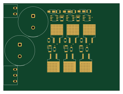
Trollerv2
rene-dev
100 × 75 mm33 parts4LGPL-3.0979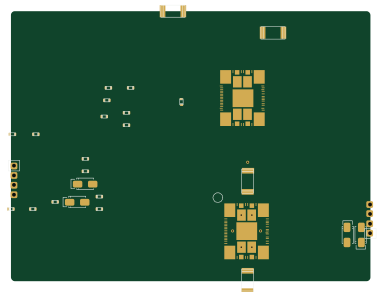
Powerstep
95.2 × 71.5 mm28 parts4LGPL-3.0979
11ua
57.3 × 19 mm26 parts2LGPL-3.0979
Diff driver
32 × 22 mm14 parts2LGPL-3.0979