
Ankle Sensor V1

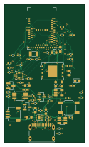
About the Ankle Sensor V1 PCB
Ankle Sensor V1 is an open source Nordic nRF PCB design by TomKuc, published on GitHub. It is a 4-layer board measuring 30 × 51.6 mm, with 59 components from 33 distinct parts.
Its main chip is the MDBT50Q-P1MV2, from the Nordic nRF family. Other key parts include the BQ25185DLHR, TPS7A2030PDBVR, LSM6DSV32XTR, W25Q01JVZEIQ and USBLC6-2SC6. By type, the board carries 25 resistors, 19 capacitors, 8 ICs, 2 transistors, 2 connectors and 1 crystal.
It belongs with the sensors and iot & wireless designs in this gallery.
From the project
CONDITIONAL READY dla3–5 prototypów JLCPCB. Można rozpocząć wycenę/import i przegląd JLCPCB. Zwolnienie wykonania wymaga zamknięcia warunków A01–A04 z raportu gotowości. Nie złożono zamówienia i nie wykonano testów sprzętowych. Nie ma jeszcze uruchomionego firmware.
CONDITIONAL READY dla3–5 prototypów JLCPCB. Można rozpocząć wycenę/import i przegląd JLCPCB. Zwolnienie wykonania wymaga zamknięcia warunków A01–A04 z raportu gotowości. Nie złożono zamówienia i nie wykonano testów sprzętowych. Nie ma jeszcze uruchomionego firmware.
Jedyna aktualna wersja: manifest A1. PCB SHA256: 1d3bb700a2b686ef68589bf3295488d2144a1d51a857cec7651e45be175a6134. Aktualna paczka: AnkleSensorV1A1PRODUCTIONREVIEW.zip**. Dawne ZIP A0/A1/AUDIT/FINAL i raporty bazowe są historią.
Main components on the Ankle Sensor V1
Ankle Sensor V1 bill of materials (BOM)
59 components, 33 distinct parts — part numbers from the project's BOM.
| Qty | Part | Footprint | Refs |
|---|---|---|---|
| 1 | BQ25185DLHR | BQ25185DLHR_DLH0010A_TILandPattern | U1 |
| 1 | TPS7A2030PDBVR | SOT-23-5 | U2 |
| 1 | MDBT50Q-P1MV2 | Raytac_MDBT50Q | U3 |
| 1 | LSM6DSV32XTR | ST_LSM6DSV32X_LGA14_3x2.5mm_P0.5mm | U4 |
| 1 | W25Q01JVZEIQ W25Q01JVZEIQ_128MiB | WSON-8-1EP_8x6mm_P1.27mm_EP3.4x4.3mm | U5 |
| 1 | USBLC6-2SC6 | SOT-23-6 | U6 |
| 1 | TLV7042DGKR | VSSOP-8_3x3mm_P0.65mm | U7 |
| 1 | TLV803EA26DBZR | SOT-23 | U8 |
| 2 | AO3400A | SOT-23 | Q1, Q2 |
| 1 | ABS07-32.768KHZ-7-T 32.768kHz CL7pF | Crystal_SMD_3215-2Pin_3.2x1.5mm | Y1 |
| 1 | TYPE-C-31-M-12 | USB_C_Receptacle_HRO_TYPE-C-31-M-12 | J1 |
| 1 | SM03B-SRSS-TB(LF)(SN) JST_SH_3P_PACK_NTC | JST_SH_SM03B-SRSS-TB_1x03-1MP_P1.00mm_Horizontal | J2 |
| 1 | SKQGABE010 | SW_SPST_SKQG_WithStem | SW1 |
| 1 | 19-217/G7C-AN1P2/6T GREEN_AlGaInP | LED_0603_1608Metric | D1 |
| 2 | CL10A225KA8NNNC 2.2u 25V X5R | C_0603_1608Metric | C1, C3 |
| 3 | CL10A106KP8NNNC 10u 10V X5R | C_0603_1608Metric | C2, C5, C9 |
| 1 | CL10A225KO8NNNC 2.2u 16V X5R | C_0603_1608Metric | C4 |
| 8 | CL05B104KO5NNNC 100n 16V X7R | C_0402_1005Metric | C6, C10, C12, C13, C15, C17, C18, C19 |
| 2 | CL05C100JB5NNNC 10p 50V C0G DRAFT | C_0402_1005Metric | C7, C8 |
| 2 | CL10A475KP8NNNC 4.7u 10V X5R | C_0603_1608Metric | C11, C16 |
Show 13 more
| Qty | Part | Footprint | Refs |
|---|---|---|---|
| 1 | CC0603KRX7R7BB105 1u 16V X7R | C_0603_1608Metric | C14 |
| 1 | 0402WGF2402TCE 24k 1% | R_0402_1005Metric | R1 |
| 1 | RC0402FR-072KL 2k 1% | R_0402_1005Metric | R2 |
| 8 | 0402WGF1003TCE 100k 1% | R_0402_1005Metric | R3, R9, R10, R12, R13, R16, R22, R24 |
| 3 | 0402WGF1002TCE 10k 1% | R_0402_1005Metric | R4, R5, R8 |
| 3 | 0402WGF1004TCE 1M 1% | R_0402_1005Metric | R6, R7, R23 |
| 1 | 0402WGF220JTCE 22R 1% DRAFT | R_0402_1005Metric | R11 |
| 2 | 0402WGF5101TCE 5.1k 1% | R_0402_1005Metric | R14, R15 |
| 1 | 0402WGF2201TCE 2.2k 1% | R_0402_1005Metric | R17 |
| 1 | ERA2AEB104X 100k 0.1% | R_0402_1005Metric | R18 |
| 2 | RT0402BRD0710KL 10k 0.1% | R_0402_1005Metric | R19, R21 |
| 1 | RT0402BRD0727K4L 27.4k 0.1% | R_0402_1005Metric | R20 |
| 1 | 0402WGF1001TCE 1k 1% | R_0402_1005Metric | R25 |
Ankle Sensor V1 design files
The KiCad project lives in the TomKuc/ASV1 repository on GitHub; these links point at the commit this page was built from.
Ankle Sensor V1: common questions
What microcontroller does the Ankle Sensor V1 use?
The Ankle Sensor V1 is built around the MDBT50Q-P1MV2, from the Nordic nRF family.
How big is the Ankle Sensor V1 PCB?
The Ankle Sensor V1 measures 30 × 51.6 mm, has 4 copper layers and is 1 mm thick.
How many components are on the Ankle Sensor V1?
59 components, from 33 distinct parts, with part numbers taken from the project's own BOM. The full bill of materials is listed on this page.
Where can I download the Ankle Sensor V1 design files?
From the TomKuc/ASV1 repository on GitHub, which has the KiCad layout, the schematic and the BOM; the links under Design files point to each one.
Can I use the Ankle Sensor V1 design in my own project?
The repository has no license, so all rights stay with TomKuc. Use it as a reference, and ask the author before reusing the design.
Can I test firmware for the Ankle Sensor V1 without the hardware?
Yes. HardLabs builds a simulation of the board from its netlist and BOM, so you can run and debug Nordic nRF firmware against it before you order a PCB.
More boards in ASV1
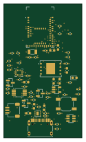 Nordic nRF
Ankle Sensor V1 before lfxo fix
30 × 51.6 mm59 parts4LNo license0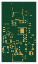 Nordic nRF
Ankle Sensor V1 before final merge
30 × 51.6 mm59 parts4LNo license0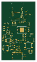 Nordic nRF
Ankle Sensor V1 before flash bypass
30 × 51.6 mm59 parts4LNo license0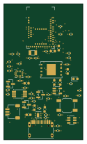 Nordic nRF
Ankle Sensor V1 before c3 via fix
30 × 51.6 mm59 parts4LNo license0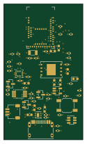 Nordic nRF
Ankle Sensor V1 routing eight open
30 × 51.6 mm59 parts4LNo license0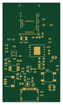 Nordic nRF
Ankle Sensor V1 fanout
30 × 51.6 mm59 parts4LNo license0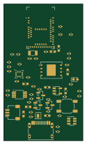 Nordic nRF
Ankle Sensor V1 placement
30 × 51.6 mm59 parts4LNo license0
Similar boards
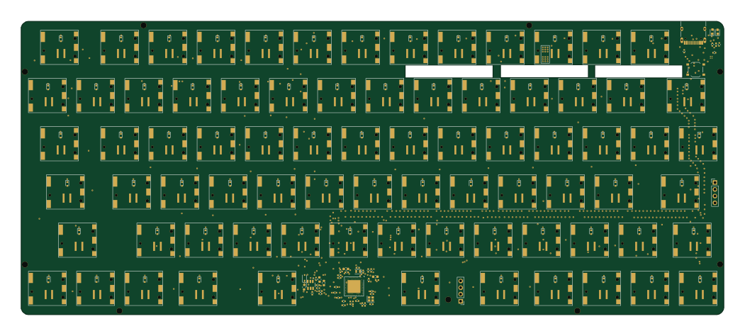 Nordic nRF
Keyboard
byrantech
262.5 × 109.6 mm206 parts2LMIT4.3k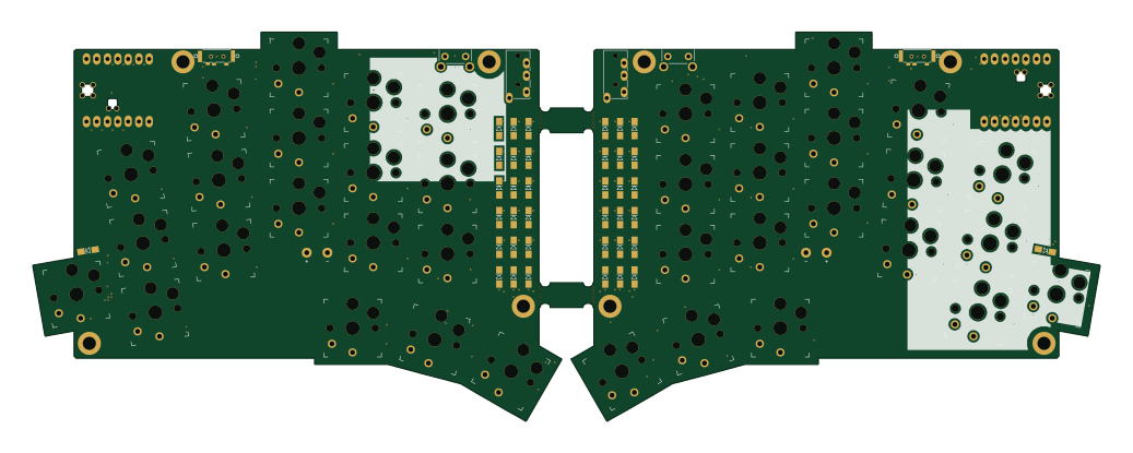 Nordic nRF
TOTEM
GEIGEIGEIST
258.8 × 94.4 mm85 parts2LCERN-OHL-P-2.02.0k Nordic nRF
Pixl.js
solosky
40 × 23 mm45 parts4LGPL-2.01.4k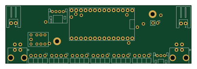 Nordic nRF
Management
dennisss
101 × 31.5 mm50 parts2LApache-2.0381 Nordic nRF
Board
363 × 128 mm420 parts4LApache-2.0381 Nordic nRF
Board hl15-latest
61 × 37 mm14 parts2LApache-2.0381