
TiNA-append

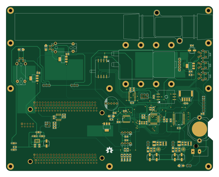
About the TiNA-append PCB
TiNA-append is an open source AVR/Arduino PCB design by wyolum, published on GitHub. It is a 2-layer board measuring 190 × 152 mm, with 135 components from 68 distinct parts.
Its main chip is the ATMEGA328-AU-ND, from the AVR/Arduino family. Other key parts include the TXB0104D, TPS62133, DS3231N, TSX0108 and CAT24C256. By type, the board carries 39 capacitors, 26 connectors, 21 resistors, 9 ICs, 8 diodes and 4 transistors.
From the project
Standalone controller for TIM (The Intelligent Matrix)
Standalone controller for TIM (The Intelligent Matrix)
To install arduino libraries: 1. download and unzip (or git clone) the files to a local directory for example, my this is /home/justin/code/TiNA 2. set your arduino sketchbook path to the arduino subdirectory of your install path by either a. editing your ~/.arduino/preferences.txt (the sketchbook.path variable) b. selecting from the "File->Preferences" drop down menu item for example, my sketchbook path is /home/justin/code/TiNA/arduino 3. start or restart the Arduino IDE
Main components on the TiNA-append
TiNA-append bill of materials (BOM)
135 components, 68 distinct parts — part numbers from the project's BOM.
| Qty | Part | Footprint | Refs |
|---|---|---|---|
| 1 | TXB0104D | TXB0104D | U1 |
| 2 | TPS62133 | TPS62132 | U3, U4 |
| 1 | DS3231N | DS3231 | U5 |
| 1 | ATMEGA328-AU-ND | TQFP32 | U7 |
| 1 | TSX0108 | TXS0108EPWR | U8 |
| 1 | CAT24C256 | SO8E | U9 |
| 1 | BEAGLEBONE | BEAGLEBONE | U10 |
| 1 | ADXL345 | ADXL345 | U11 |
| 4 | BCP5416TA | SOT223 | Q1, Q2, Q3, Q4 |
| 1 | 16MHz | Xtal_SMD3 | X1 |
| 2 | 5V_EXT | Header_2 | J1, J2 |
| 1 | addr | Header_2x2 | J3 |
| 1 | AREF | ShortLink2 | P1 |
| 1 | ICSP | Header_ISP | P4 |
| 1 | FTDI | Header_FTDI | P5 |
| 1 | GAGE_PR | HCEM500GUH9P3 | P7 |
| 1 | ABSO_PR | HDIB002AUY8H5 | P8 |
| 2 | C3SB | pin_strip_4-90 | P9, P10 |
| 1 | VSel_Vlv | Header_3 | P11 |
| 1 | PWR_IN | Header_2 | P13 |
Show 48 more
| Qty | Part | Footprint | Refs |
|---|---|---|---|
| 1 | X_VALVE | X_Valve_2 | P14 |
| 1 | Flow_Conn | Conn_Flow_SFM3000_Male | P15 |
| 1 | FLOWMETER | FlowMeter_CFM3000 | P16 |
| 1 | PUMP | Pump_P54E01R_02 | P17 |
| 1 | U6_OE | ShortLink2 | P19 |
| 1 | 5V_LINK | ShortLink2 | P20 |
| 2 | CONN_23X2 | PIN_ARRAY_23X2 | P21, P22 |
| 1 | Alt_Add | ShortLink2 | P23 |
| 1 | PWR_IN | JACK_ALIM | P24 |
| 1 | Int1 | ShortLink2 | P28 |
| 1 | Int2 | ShortLink2 | P29 |
| 1 | VSel_Vlv2 | Header_3 | P34 |
| 1 | X_VALVE2 | X_Valve_2 | P38 |
| 3 | I_O | I_O | B1, B2, B3 |
| 2 | PB0 | I_O | B4, B12 |
| 1 | PC0 | I_O | B8 |
| 1 | PC1 | I_O | B9 |
| 1 | PC6 | I_O | B10 |
| 1 | PC7 | I_O | B11 |
| 1 | BATT_HOLDER | CR2032 | BT1 |
| 1 | PCB | PCB | PCB1 |
| 10 | SCREW | vite_3mm | SC1, SC2, SC3, SC4, SC5, SC6, SC7, SC8 +2 |
| 1 | BUZZER | Speaker | SP1 |
| 1 | Reset | SW_PB_V_H | SW1 |
| 1 | INT0 | SW_PB_V_H | SW2 |
| 1 | INT1 | SW_PB_V_H | SW3 |
| 4 | 1N4007 | diode-DO214AC | D1, D3, D4, D9 |
| 1 | 5V0 | led_0805 | D5 |
| 1 | 3V3 | led_0805 | D6 |
| 1 | BLINK | led_0805 | D7 |
| 1 | 12V | led_0805 | D8 |
| 2 | 2u2H,3.0A | Inductor_SMD3 | L1, L2 |
| 21 | 100n | c_0805 | C1, C4, C5, C7, C8, C9, C10, C11 +13 |
| 2 | 22p | c_0603 | C2, C3 |
| 4 | 100nF | c_0805 | C18, C20, C32, C34 |
| 2 | 22uF X7R | c_1210 | C19, C33 |
| 2 | 3.3nF | c_0805 | C21, C35 |
| 4 | 100uF | C_ELCO_SMD | C22, C26, C36, C37 |
| 2 | 100u,16V | C_ELCO_SMD | C27, C42 |
| 2 | 10uF X7R | c_1206 | C30, C38 |
| 8 | 10k | r_0805 | R1, R2, R3, R4, R11, R15, R21, R22 |
| 1 | 4k7 | r_0805 | R5 |
| 3 | 1k | r_0805 | R6, R10, R13 |
| 2 | 100k | r_0805 | R7, R14 |
| 1 | 330E | r_0805 | R8 |
| 1 | 120E | r_0805 | R9 |
| 3 | 4k75 | r_0805 | R16, R17, R18 |
| 2 | 1k5 | r_0805 | R19, R20 |
TiNA-append design files
The KiCad project lives in the wyolum/TiNA repository on GitHub; these links point at the commit this page was built from.
TiNA-append: common questions
What microcontroller does the TiNA-append use?
The TiNA-append is built around the ATMEGA328-AU-ND, from the AVR/Arduino family.
How big is the TiNA-append PCB?
The TiNA-append measures 190 × 152 mm, has 2 copper layers and is 1.6 mm thick.
How many components are on the TiNA-append?
135 components, from 68 distinct parts, with part numbers taken from the project's own BOM. The full bill of materials is listed on this page.
Where can I download the TiNA-append design files?
From the wyolum/TiNA repository on GitHub, which has the KiCad layout and the BOM; the links under Design files point to each one.
Can I use the TiNA-append design in my own project?
The repository has no license, so all rights stay with wyolum. Use it as a reference, and ask the author before reusing the design.
Can I test firmware for the TiNA-append without the hardware?
Yes. HardLabs builds a simulation of the board from its netlist and BOM, so you can run and debug AVR/Arduino firmware against it before you order a PCB.
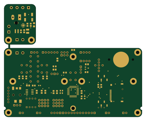
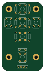
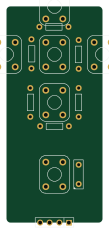
More boards in TiNA
Similar boards
 AVR/Arduino
Magspoof
samyk
35 × 29 mm11 parts2LNo license4.2k AVR/Arduino
Redox keyboard
mattdibi
162.2 × 126.5 mm77 parts2LMIT2.0k AVR/Arduino
Labrador
espotek-org
36.8 × 34.7 mm75 parts2LNo license1.2k AVR/Arduino
ModuleV450
stuartpittaway
30 × 61.4 mm39 parts2LCC-BY-NC-4.01.1k AVR/Arduino
V4
30 × 50 mm38 parts2LCC-BY-NC-4.01.1k AVR/Arduino
Discipline
coseyfannitutti
304.9 × 122.8 mm170 parts2LCC-BY-NC-4.01.0k