
DIY-amplifier

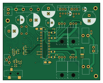
About the DIY-amplifier PCB
DIY-amplifier is an open source PCB design by adamkral20-svg, published on GitHub. It is a 4-layer board measuring 90.9 × 71.6 mm, with 91 components from 42 distinct parts.
Other key parts include the 74LVC1G14, OPA310SXDBV, HIP4081A, 74LVC1G17 and L7805. By type, the board carries 29 capacitors, 29 resistors, 11 ICs, 10 transistors, 4 diodes and 3 connectors.
It belongs with the audio designs in this gallery.
From the project
Custom class-d amplifier board
It uses 4 MOSFETS in an H-bridge configuration, allowing for BTL output and thus higher power from lower supply voltage. The main part is the HIP-4081A H-bridge MOSFET gate driver. It can reliably drive the MOSFETS in the hundreds of kHz switching speed.
The onboard discrete oscillator should be around 200kHz. It uses a pnp constant current source connected to a capacitor, and a MOSFET to discharge the capacitor quickly to generate a Ramp wave. The MOSFET has 0.7nC gate charge, so the TLV3501 can reliably drive it with its output current capability.
Main components on the DIY-amplifier
DIY-amplifier bill of materials (BOM)
91 components, 42 distinct parts — part numbers from the project's BOM.
| Qty | Part | Footprint | Refs |
|---|---|---|---|
| 2 | 74LVC1G14 | SOT-23-5 | U1, U11 |
| 1 | OPA310SXDBV OPA310SxDBV | SOT-23-6 | U2 |
| 1 | HIP4081A | DIP-20_W7.62mm | U3 |
| 2 | 74LVC1G17 | SOT-23-5 | U4, U9 |
| 1 | L7805 | TO-220-3_Vertical | U5 |
| 1 | L7812 | TO-220-3_Vertical | U6 |
| 1 | TLV3501AIDBV | SOT-23-6 | U7 |
| 1 | MCP6561U | SOT-23-5 | U8 |
| 1 | INA181 | SOT-23-6 | U10 |
| 4 | IRF540N | TO-220-3_Horizontal_TabUp | Q1, Q2, Q3, Q4 |
| 1 | DMN2310U | SOT-23 | Q5 |
| 3 | BC858 | SOT-23 | Q6, Q7, Q9 |
| 1 | BC848 | SOT-23 | Q8 |
| 1 | PJA3431 | SOT-23-3 | Q10 |
| 1 | AUDIOPLUG3 AudioPlug3 | Jack_3.5mm_CUI_SJ-3523-SMT_Horizontal | J1 |
| 1 | Output | TerminalBlock_4Ucon_1x02_P3.50mm_Horizontal | J2 |
| 1 | Input | TerminalBlock_4Ucon_1x02_P3.50mm_Horizontal | J3 |
| 1 | 6A | Fuseholder_Clip-5x20mm_Eaton_1A5601-01_Inline_P20.80x6.76mm_D1.70mm_Horizontal | F1 |
| 1 | 68K 68k | Potentiometer_ACP_CA9-H2,5_Horizontal | RV1 |
| 1 | SW_Push | SW_PUSH_6mm_H13mm | SW1 |
Show 22 more
| Qty | Part | Footprint | Refs |
|---|---|---|---|
| 2 | CDBA3100-HF | D_SMA | D1, D2 |
| 2 | 1N4148WT | D_SOD-523 | D4, D5 |
| 2 | 47U 47u | L_Toroid_Vertical_L14.0mm_W6.3mm_P4.57mm_Pulse_A | L1, L2 |
| 1 | 1n | C_0402_1005Metric | C1 |
| 11 | 0.1U 0.1u | C_0402_1005Metric | C2, C4, C6, C7, C8, C9, C10, C24 +3 |
| 3 | 10U 10u | C_0402_1005Metric | C3, C5, C35 |
| 4 | 0.1U 0.1u | C_Disc_D3.0mm_W1.6mm_P2.50mm | C11, C18, C20, C21 |
| 2 | 10U 10u | CP_Radial_D4.0mm_P2.00mm | C12, C17 |
| 4 | 1000U 1000u | CP_Radial_D12.5mm_P5.00mm | C13, C15, C19, C26 |
| 2 | 100U 100u | CP_Radial_D8.0mm_P3.50mm | C14, C16 |
| 2 | 1.5U 1.5u | C_Disc_D3.0mm_W1.6mm_P2.50mm | C22, C23 |
| 1 | 2.7K 2.7k | R_0603_1608Metric | R1 |
| 1 | 3.3K 3.3k | R_0603_1608Metric | R2 |
| 13 | 10K 10k | R_0603_1608Metric | R3, R9, R11, R16, R17, R20, R22, R23 +5 |
| 2 | 470 | R_0603_1608Metric | R4, R25 |
| 2 | 220K 220k | R_0603_1608Metric | R5, R6 |
| 4 | 10 | R_1206_3216Metric | R7, R8, R18, R19 |
| 1 | 150 | R_0603_1608Metric | R10 |
| 1 | 100K 100k | R_0603_1608Metric | R12 |
| 1 | 81K 81k | R_0603_1608Metric | R13 |
| 2 | 22K 22k | R_0603_1608Metric | R14, R15 |
| 1 | 0.03 | R_2512_6332Metric | R21 |
DIY-amplifier design files
The KiCad project lives in the adamkral20-svg/DIY-amplifier repository on GitHub; these links point at the commit this page was built from.
- Layouthardware/DIY amplifier.kicad_pcb
- Schematichardware/DIY amplifier.kicad_sch
- BOMBOM.csv
DIY-amplifier: common questions
How big is the DIY-amplifier PCB?
The DIY-amplifier measures 90.9 × 71.6 mm, has 4 copper layers and is 1.6 mm thick.
How many components are on the DIY-amplifier?
91 components, from 42 distinct parts, with part numbers taken from the project's own BOM. The full bill of materials is listed on this page.
Where can I download the DIY-amplifier design files?
From the adamkral20-svg/DIY-amplifier repository on GitHub, which has the KiCad layout, the schematic and the BOM; the links under Design files point to each one.
Can I use the DIY-amplifier design in my own project?
The repository has no license, so all rights stay with adamkral20-svg. Use it as a reference, and ask the author before reusing the design.
Similar boards
KLOR
GEIGEIGEIST
160.2 × 118.3 mm79 parts2LGPL-3.01.2k
ButtonsLEDs
shanteacontrols
390 × 37 mm82 parts2LApache-2.0956
USB
52 × 12.6 mm6 parts2LApache-2.0956
Pots
390 × 93 mm75 parts2LApache-2.0956
PicoGUS Hand386
polpo
29.2 × 75.2 mm43 parts4LGPL-2.0800
Snark barker
schlae
231.1 × 106.7 mm193 parts2LNo license687