
Ir receiver

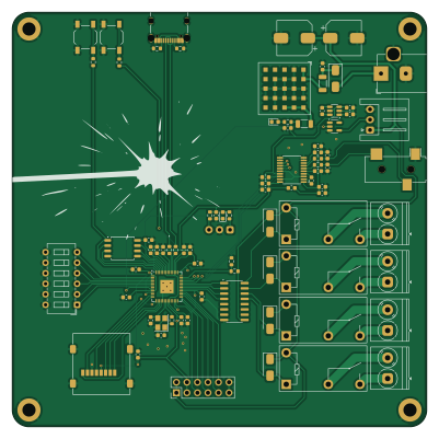
About the Ir receiver PCB
Ir receiver is an open source RP2040/RP2350 PCB design by adeboni, published on GitHub. It is a 2-layer board measuring 100 × 100 mm, with 84 components from 48 distinct parts.
Its main chip is the RP2040, from the RP2040/RP2350 family. Other key parts include the RPM3.3-6.0, DRV8871DDA, W25Q128JVS, MAX98357A and AP3602. By type, the board carries 34 capacitors, 14 resistors, 10 connectors, 8 ICs, 7 diodes and 4 relays.
It belongs with the robotics & motion, audio and iot & wireless designs in this gallery.
From the project
This repository stores code for various electronics projects I've made
This repository stores code for various electronics projects I've made
Wasp Cannon: A wifi-enabled water cannon for shooting water at wasps on my balcony CV Glove: A glove with flex sensors on fingers that output control voltages for eurorack modules Critter Coat: A coat with fluttering butterflies on it AQI Monitor: Simple air quality monitor using a Honeywell HPM sensors Atari Controller: Custom Atari 2600 controller with an analog joystick Camera Remote: Wireless camera shutter control Gas Sensor: A generic MQ gas sensor board with LED indicators PS2 Drone Controller: Lets you control…
Main components on the Ir receiver
Ir receiver bill of materials (BOM)
84 components, 48 distinct parts — part numbers from the project's BOM.
| Qty | Part | Footprint | Refs |
|---|---|---|---|
| 1 | RPM3.3-6.0 | Converter_DCDC_RECOM_RPMx.x-x.0 | U1 |
| 1 | DRV8871DDA TSOP58038 | Vishay_MINICAST-3Pin | U2 |
| 1 | RP2040 | QFN-56-1EP_7x7mm_P0.4mm_EP3.2x3.2mm | U3 |
| 1 | W25Q128JVS | SOIC-8_5.3x5.3mm_P1.27mm | U4 |
| 1 | MAX98357A PCM5100A | TSSOP-20_4.4x6.5mm_P0.65mm | U5 |
| 1 | AP3602 | SOT-23-6 | U6 |
| 1 | 74LVC1G34 | SOT-23-5 | U7 |
| 1 | TSOP58038 ULN2003 | SOIC-16_3.9x9.9mm_P1.27mm | U8 |
| 1 | 12MHZ 12MHz | Crystal_SMD_3225-4Pin_3.2x2.5mm | Y1 |
| 1 | 0472192001 | microSD_HC_Molex_47219-2001 | J1 |
| 1 | AudioJack3 | Jack_3.5mm_CUI_SJ-3523-SMT_Horizontal | J2 |
| 1 | Barrel_Jack_Switch | BarrelJack_Horizontal | J3 |
| 1 | Conn_01x03 | JST_XH_S3B-XH-A_1x03_P2.50mm_Horizontal | J4 |
| 1 | USB_C_RECEPTACLE_USB2.0 USB_C_Receptacle_USB2.0 | USB_C_Receptacle_Palconn_UTC16-G | J5 |
| 1 | CONN_01X03 Screw_Terminal_01x02 | TerminalBlock_Phoenix_PT-1,5-2-5.0-H_1x02_P5.00mm_Horizontal | J6 |
| 3 | Screw_Terminal_01x02 | TerminalBlock_Phoenix_PT-1,5-2-5.0-H_1x02_P5.00mm_Horizontal | J7, J8, J9 |
| 1 | Conn_02x06_Odd_Even | PinHeader_2x06_P2.54mm_Vertical | J10 |
| 4 | G5Q-1A | Relay_SPST_Omron-G5Q-1A | K1, K2, K3, K4 |
| 2 | SW_Push | SW_SPST_TL3342 | SW1, SW2 |
| 1 | SW_DIP_x06 | SW_DIP_SPSTx06_Slide_6.7x16.8mm_W7.62mm_P2.54mm_LowProfile | SW3 |
Show 28 more
| Qty | Part | Footprint | Refs |
|---|---|---|---|
| 1 | LED | LED_0603_1608Metric | D2 |
| 1 | SS34 LED | LED_0603_1608Metric | D3 |
| 5 | SS34 | D_SMA | D4, D5, D6, D7, D8 |
| 2 | BLM31SN500SN1L | L_1206_3216Metric | FB1, FB2 |
| 1 | FerriteBead | L_0603_1608Metric | FB3 |
| 1 | 22U 10u | C_0603_1608Metric | C1 |
| 1 | 22u | C_0603_1608Metric | C2 |
| 4 | 10U 10u | C_0603_1608Metric | C3, C37, C41, C52 |
| 9 | 100N 100n | C_0603_1608Metric | C4, C5, C6, C7, C8, C12, C13, C14 +1 |
| 1 | 10U 100n | C_0603_1608Metric | C9 |
| 4 | 1u | C_0603_1608Metric | C10, C11, C40, C44 |
| 1 | 100N 470u 16V | CP_Elec_8x10 | C15 |
| 1 | 470u 16V | CP_Elec_8x10 | C16 |
| 2 | 27P 27p | C_0603_1608Metric | C23, C27 |
| 3 | 100n | C_0603_1608Metric | C38, C45, C46 |
| 3 | 10u | C_0603_1608Metric | C39, C47, C48 |
| 2 | 2.2u | C_0603_1608Metric | C43, C49 |
| 2 | 2.2n | C_0603_1608Metric | C50, C51 |
| 1 | 3.3R 5.1k | R_0603_1608Metric | R1 |
| 1 | 10K 5.1k | R_0603_1608Metric | R2 |
| 1 | 4.7K 27 | R_0603_1608Metric | R3 |
| 1 | 100 | R_0603_1608Metric | R4 |
| 2 | 5.1K 4.7k | R_0603_1608Metric | R5, R7 |
| 1 | 27 | R_0603_1608Metric | R6 |
| 1 | 30K 4.7k | R_0603_1608Metric | R8 |
| 1 | 1000 | R_0603_1608Metric | R9 |
| 3 | 1k | R_0603_1608Metric | R17, R22, R23 |
| 2 | 470 | R_0603_1608Metric | R34, R42 |
Ir receiver design files
The KiCad project lives in the adeboni/electronics repository on GitHub; these links point at the commit this page was built from.
Ir receiver: common questions
What microcontroller does the Ir receiver use?
The Ir receiver is built around the RP2040, from the RP2040/RP2350 family.
How big is the Ir receiver PCB?
The Ir receiver measures 100 × 100 mm, has 2 copper layers and is 1.6 mm thick.
How many components are on the Ir receiver?
84 components, from 48 distinct parts, with part numbers taken from the project's own BOM. The full bill of materials is listed on this page.
Where can I download the Ir receiver design files?
From the adeboni/electronics repository on GitHub, which has the KiCad layout, the schematic and the BOM; the links under Design files point to each one.
Can I use the Ir receiver design in my own project?
The repository has no license, so all rights stay with adeboni. Use it as a reference, and ask the author before reusing the design.
Can I test firmware for the Ir receiver without the hardware?
Yes. HardLabs builds a simulation of the board from its netlist and BOM, so you can run and debug RP2040/RP2350 firmware against it before you order a PCB.
More boards in electronics
 RP2040/RP2350
Ir transmitter
114.3 × 25.4 mm81 parts2LNo license0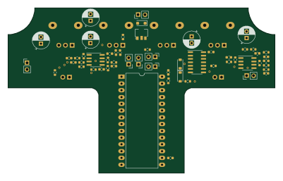
Looper
100 × 62 mm63 parts2LNo license0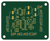
Alien screamer
50 × 40 mm55 parts2LNo license0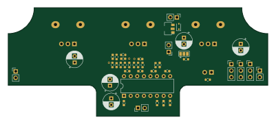
Delay reverb
100 × 42 mm46 parts2LNo license0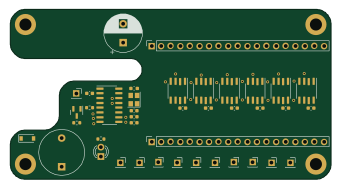
Drone tranceiver
85 × 45 mm40 parts2LNo license0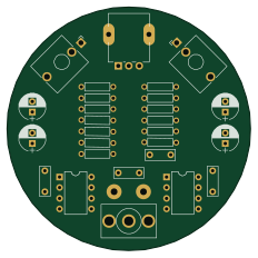
Tape jar
58 × 58 mm28 parts2LNo license0
Aw rachio adapter
23.1 × 51 mm19 parts2LNo license0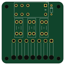
Fiat light relay
52 × 52 mm7 parts2LNo license0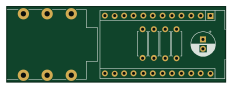 AVR/Arduino
Drum trigger adapter
58 × 20 mm7 parts2LNo license0
Dc dc jack converter
30.8 × 12.2 mm5 parts2LNo license0
Tape jar fp
68 × 68 mm3 parts2LNo license0
Similar boards
 RP2040/RP2350
Open Book Abridged Edition
joeycastillo
85 × 115 mm29 parts2LCC-BY-SA-4.08.1k RP2040/RP2350
Corne
foostan
277.2 × 107.5 mm164 parts2LCC-BY-4.07.7k RP2040/RP2350
Corne
277.2 × 107.5 mm164 parts2LCC-BY-4.07.7k RP2040/RP2350
Jitx design
gusmanb
55.5 × 65 mm26 parts4LGPL-3.05.0k RP2040/RP2350
LogicAnalyzer
57 × 55.2 mm6 parts2LGPL-3.05.0k RP2040/RP2350
Main
google
98 × 71 mm102 parts2LApache-2.02.9k