
Rc car

About the Rc car PCB
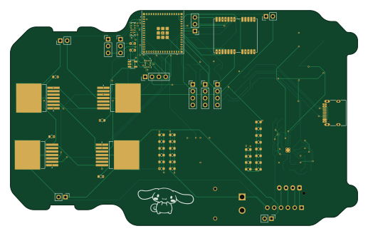
Rc car is an open source ESP32 PCB design by alaotach, published on GitHub. It is a 4-layer board measuring 129 × 79.8 mm, with 85 components from 39 distinct parts.
Its main chip is the ESP32-S3-MINI-1, from the ESP32 family. Other key parts include the AP2112K-3.3, NEO-M8M, IP2721, BQ24650 and LM2596S-5. By type, the board carries 31 capacitors, 21 resistors, 15 connectors, 12 ICs, 2 transistors and 2 diodes.
It belongs with the sensors, displays & leds and power & battery designs in this gallery.
From the project
Quixie is a small autonomous RC delivery car. The custom PCB handles motor control and sensor expansion; the firmware manages navigation, telemetry, and the locking cargo bay.
Quixie is a small autonomous RC delivery car. The custom PCB handles motor control and sensor expansion; the firmware manages navigation, telemetry, and the locking cargo bay.
- Servo locked cargo bay - lid opens and closes automatically via servo motor - Live camera feed - ESP32 cam stream on dashboard - GPS navigation - Neo6M position tracking - Obstacle avoidance - 3× ultrasonic sensors - OLED display - SSD1306 1.3" ---
Main components on the Rc car
Rc car bill of materials (BOM)
85 components, 39 distinct parts — part numbers from the project's BOM.
| Qty | Part | Footprint | Refs |
|---|---|---|---|
| 1 | ESP32-S3-MINI-1 | ESP32-S2-MINI-1 | U1 |
| 1 | AP2112K-3.3 | SOT-23-5 | U2 |
| 1 | NEO-M8M | ublox_NEO | U3 |
| 1 | IP2721 | TSSOP-16_4.4x5mm_P0.65mm | U4 |
| 1 | BQ24650 | Texas_RVA_VQFN-16-1EP_3.5x3.5mm_P0.5mm_EP2.14x2.14mm_ThermalVias | U5 |
| 1 | LM2596S-5 | TO-263-5_TabPin3 | U6 |
| 1 | TMF8828 | AMS_OLGA12 | U7 |
| 1 | BMI270 | XDCR_BMI270 | U8 |
| 4 | BTN7960B_LA | IC_BTN7960B | U9, U10, U11, U12 |
| 2 | Q_NMOS_GDS | TO-263-2 | Q1, Q2 |
| 1 | UART | PinHeader_1x03_P2.54mm_Vertical | J1 |
| 3 | Ultrasonic | PinHeader_1x04_P2.54mm_Vertical | J2, J4, J5 |
| 1 | OLED | PinHeader_1x04_P2.54mm_Vertical | J3 |
| 2 | Servo | PinHeader_1x03_P2.54mm_Vertical | J6, J7 |
| 1 | BMS | PinHeader_1x06_P2.54mm_Vertical | J8 |
| 2 | motor | PinHeader_1x02_P2.54mm_Vertical | J9, J14 |
| 2 | motor2 | PinHeader_1x02_P2.54mm_Vertical | J10, J15 |
| 1 | Battery | JST_XH_B4B-XH-AM_1x04_P2.50mm_Vertical | J11 |
| 1 | XT30PW-M | AMASS_XT30PW-M | J12 |
| 1 | USB_C_RECEPTACLE_USB2.0_14P USB_C_Receptacle_USB2.0_14P | USB_C_Receptacle_HRO_TYPE-C-31-M-12 | J13 |
Show 19 more
| Qty | Part | Footprint | Refs |
|---|---|---|---|
| 1 | Thermistor | R_0805_2012Metric | TH1 |
| 2 | LED | LED_0201_0603Metric | D1, D2 |
| 1 | 10UH 10uH | L_0201_0603Metric | L1 |
| 10 | 100NF 100nF | C_0603_1608Metric | C1, C4, C10, C12, C13, C20, C27, C34 +2 |
| 11 | 10UF 10uF | C_0603_1608Metric | C2, C3, C9, C11, C19, C23, C24, C26 +3 |
| 3 | 1UF 1uF | C_0603_1608Metric | C5, C6, C7 |
| 1 | 22PF 22pF | C_0603_1608Metric | C8 |
| 2 | 220UF 220uF | C_0603_1608Metric | C14, C15 |
| 4 | 470UF 470uF | C_0603_1608Metric | C25, C32, C37, C42 |
| 3 | 1KOHM 1kOhm | R_0603_1608Metric_Pad0.98x0.95mm_HandSolder | R1, R4, R6 |
| 3 | 2KOHM 2kOhm | R_0603_1608Metric_Pad0.98x0.95mm_HandSolder | R2, R3, R5 |
| 2 | 5.1KOHM 5.1kOhm | R_0603_1608Metric_Pad0.98x0.95mm_HandSolder | R7, R9 |
| 6 | 10KOHM 10kOhm | R_0603_1608Metric | R10, R11, R12, R13, R14, R15 |
| 1 | 5.23KOHM 5.23kOhm | R_0603_1608Metric | R16 |
| 1 | 30.1KOHM 30.1kOhm | R_0603_1608Metric | R17 |
| 1 | 20MOHM 20mOhm | R_0603_1608Metric | R18 |
| 2 | 499KOHM 499kOhm | R_0603_1608Metric | R19, R21 |
| 1 | 100KOHM 100kOhm | R_0603_1608Metric | R20 |
| 1 | 36KOHM 36kOhm | R_0603_1608Metric | R22 |
Rc car design files
The KiCad project lives in the alaotach/rc-car repository on GitHub; these links point at the commit this page was built from.
- Layoutpcb/rc-car.kicad_pcb
- Schematicpcb/rc-car.kicad_sch
- BOMdocs/rc-car-BOM.csv
Rc car: common questions
What microcontroller does the Rc car use?
The Rc car is built around the ESP32-S3-MINI-1, from the ESP32 family.
How big is the Rc car PCB?
The Rc car measures 129 × 79.8 mm, has 4 copper layers and is 1.6 mm thick.
How many components are on the Rc car?
85 components, from 39 distinct parts, with part numbers taken from the project's own BOM. The full bill of materials is listed on this page.
Where can I download the Rc car design files?
From the alaotach/rc-car repository on GitHub, which has the KiCad layout, the schematic and the BOM; the links under Design files point to each one.
Can I use the Rc car design in my own project?
The repository has no license, so all rights stay with alaotach. Use it as a reference, and ask the author before reusing the design.
Can I test firmware for the Rc car without the hardware?
Yes. HardLabs builds a simulation of the board from its netlist and BOM, so you can run and debug ESP32 firmware against it before you order a PCB.
Similar boards
 ESP32
ESP32Open Book Abridged Edition
joeycastillo
85 × 115 mm65 parts2LCC-BY-SA-4.08.1k ESP32
ESP32Esp32 minimal
atopile
36.2 × 26.8 mm20 parts2LMIT4.0k ESP32
ESP32Badge
56.3 × 39 mm239 parts4LMIT4.0k ESP32
ESP32Controller
StuckAtPrototype
29 × 74 mm58 parts4LApache-2.03.8k ESP32
ESP32Racer
36 × 50.2 mm70 parts4LApache-2.03.8k ESP32
ESP32Bitaxe
skot
56.5 × 99.8 mm86 parts4LCERN-OHL-S-2.01.4k