
Lightclock

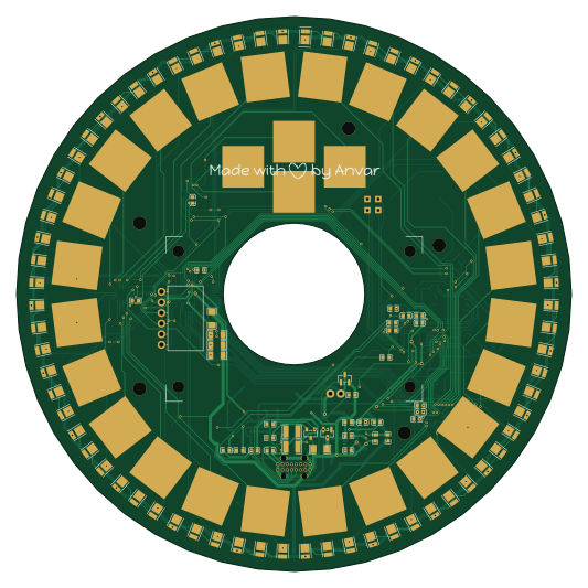
About the Lightclock PCB
Lightclock is an open source RP2040/RP2350 PCB design by Anvarys, published on GitHub. It is a 2-layer board measuring 133 × 133 mm, with 191 components from 45 distinct parts.
Its main chip is the RP2040, from the RP2040/RP2350 family. Other key parts include the STP24DP05BTR, CH224K, TPS62160DGKR, SX3B12.000F1210F30 and W25Q64JVSSIQ. By type, the board carries 72 LEDs, 35 capacitors, 28 resistors, 12 ICs, 3 transistors and 2 diodes.
It belongs with the displays & leds and sensors designs in this gallery.
From the project
A custom PCB-based Clock/Alarm with a 3d printed enclosure. It features a runrise alarm option (72 LEDs), a 2.42" OLED display, many capacitive touch controls (24 around in a circle and 4 for the main controls) and a buzzer.
A custom PCB-based Clock/Alarm with a 3d printed enclosure. It features a runrise alarm option (72 LEDs), a 2.42" OLED display, many capacitive touch controls (24 around in a circle and 4 for the main controls) and a buzzer.
I made this project because I wanted to have a runrise alarm to wake up more naturally and also be easy to set up alarms with few clicks and without any additional installation required.
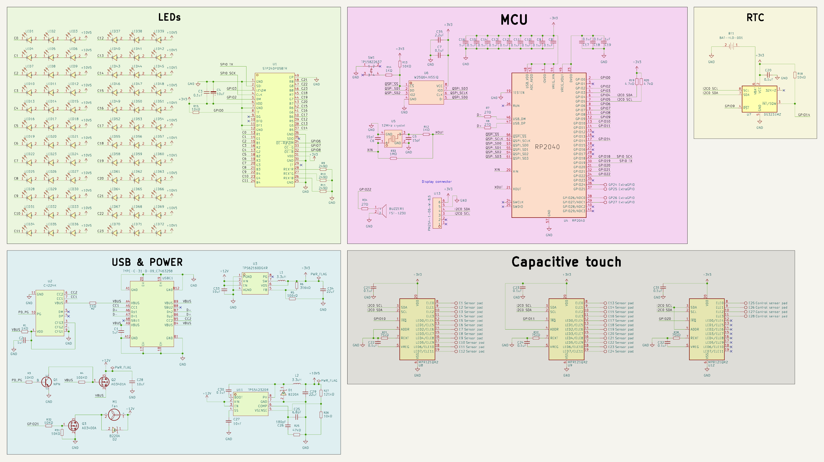
Main components on the Lightclock
Lightclock bill of materials (BOM)
191 components, 45 distinct parts — part numbers from the project's BOM.
| Qty | Part | Footprint | Refs |
|---|---|---|---|
| 1 | STP24DP05BTR ST(意法半导体) | TQFP-48_L7.0-W7.0-P0.50-LS9.0-BL-EP3.5 | U1 |
| 1 | CH224K WCH(南京沁恒) | ESSOP-10_L4.9-W3.9-P1.0-LS6.0-TL-EP | U2 |
| 1 | TPS62160DGKR TI(德州仪器) | MSOP-8_L3.0-W3.0-P0.65-LS5.0-BL | U3 |
| 1 | RP2040 | QFN-56-1EP_7x7mm_P0.4mm_EP3.2x3.2mm | U4 |
| 1 | SX3B12.000F1210F30 12MHz crystal SCTF(星通时频) | CRYSTAL-SMD_4P-L3.2-W2.5-BL | U5 |
| 1 | W25Q64JVSSIQ Winbond(华邦) | SOP-8_L5.3-W5.3-P1.27-LS8.0-BL | U6 |
| 1 | DS3231MZ | SOIC-8_3.9x4.9mm_P1.27mm | U7 |
| 3 | MPR121QR2 | QFN-20_L3.0-W3.0-P0.40-BL | U8, U9, U12 |
| 1 | TPS54232DR TI(德州仪器) | SOIC-8_L4.9-W3.9-P1.27-LS6.0-BL | U11 |
| 1 | PM254-1-06-W-8.5 HCTL(华灿天禄) | HDR-TH_6P-P2.54-H-F-W10.0-N | U13 |
| 1 | Fan | SMD_2pads_polar_4mm_square | M1 |
| 1 | NPN | SOT-23-3_L2.9-W1.3-P1.90-LS2.4-BR | Q1 |
| 1 | AO3401A | SOT-23 | Q2 |
| 1 | AO3400A | SOT-23 | Q3 |
| 1 | BAT-HLD-001 TE Connectivity(泰科电子) | BAT-SMD_BAT-HLD-001 | BT1 |
| 1 | FUET-1230 FST-1230 FUET(福声科技) | BUZ-SMD_L12.0-W12.0_FUET-1230 | BUZZER1 |
| 24 | Sensor pad | capacitive-touch-pad-trapezoid | E1, E2, E3, E4, E5, E6, E7, E8 +16 |
| 4 | Control sensor pad | capacitive-touch-pad-square10mm | E25, E26, E27, E28 |
| 4 | ExtraGPIO | TestPoint_THTPad_1.5x1.5mm_Drill0.7mm | GP24, GP25, GP26, GP27 |
| 1 | TP15822637 ROCPU Switches(台普) | SW-SMD_4P-L5.2-W5.2-P3.70-LS6.4 | SW1 |
Show 25 more
| Qty | Part | Footprint | Refs |
|---|---|---|---|
| 1 | TYPE-C-31-D-09 TYPE-C-31-D-09_C7463258 韩国韩荣 | USB-C-TH_TYPE-C-31-D-09 | USBC1 |
| 72 | GW JTLMS1.EM-GVH3-XX57-1-60-R33 OSRAM(欧司朗) | LED-SMD_L3.5-W2.8-RD_GW-JTLRS1.EM-K5L4-XX57-1 | LED1, LED2, LED3, LED4, LED5, LED6, LED7, LED8 +64 |
| 2 | B220A-13-F B220A DIODES(美台) | SMA_L4.4-W2.8-LS5.4-RD | D1, D2 |
| 2 | 3.3UH 3.3uH | IND-SMD_L7.0-W6.6 | L1, L2 |
| 4 | 1UF 1uF | C0603 | C1, C2, C16, C19 |
| 20 | 0.1UF 0.1uF | C0603 | C3, C7, C8, C9, C10, C11, C12, C13 +12 |
| 3 | 10UF 10uF | C1206 | C4, C28, C33 |
| 2 | 15PF 15pF | C0603 | C5, C6 |
| 1 | 6.8PF 6.8pF | C0603 | C25 |
| 1 | 180PF 180pF | C0603 | C26 |
| 1 | 10NF 10nF | C0603 | C27 |
| 2 | 22UF 22uF | C0805 | C29, C34 |
| 1 | 2.2UF 2.2uF | C0805 | C35 |
| 2 | 1KΩ | R1210 | R1, R2 |
| 7 | 10KΩ | R0603 | R3, R13, R15, R18, R26, R31, R32 |
| 2 | 100KΩ | R0603 | R4, R5 |
| 1 | 316kΩ | R0603 | R6 |
| 3 | 27Ω | R0603 | R7, R8, R34 |
| 3 | 249Ω | R1206 | R9, R10, R11 |
| 2 | 1KΩ | R0603 | R12, R14 |
| 2 | 4.7kΩ | R0603 | R19, R20 |
| 3 | 75kΩ | R0603 | R21, R22, R28 |
| 1 | 47kΩ | R0603 | R25 |
| 1 | 121kΩ | R0603 | R27 |
| 1 | 1MΩ | R0603 | R33 |
Lightclock design files
The KiCad project lives in the Anvarys/lightclock repository on GitHub; these links point at the commit this page was built from.
- LayoutPCB/lightclock.kicad_pcb
- SchematicPCB/lightclock.kicad_sch
- BOMPCB/export/kicad_bom.csv
Lightclock: common questions
What microcontroller does the Lightclock use?
The Lightclock is built around the RP2040, from the RP2040/RP2350 family.
How big is the Lightclock PCB?
The Lightclock measures 133 × 133 mm, has 2 copper layers and is 1.6 mm thick.
How many components are on the Lightclock?
191 components, from 45 distinct parts, with part numbers taken from the project's own BOM. The full bill of materials is listed on this page.
Where can I download the Lightclock design files?
From the Anvarys/lightclock repository on GitHub, which has the KiCad layout, the schematic and the BOM; the links under Design files point to each one.
Can I use the Lightclock design in my own project?
The repository has no license, so all rights stay with Anvarys. Use it as a reference, and ask the author before reusing the design.
Can I test firmware for the Lightclock without the hardware?
Yes. HardLabs builds a simulation of the board from its netlist and BOM, so you can run and debug RP2040/RP2350 firmware against it before you order a PCB.
Similar boards
 RP2040/RP2350
Open Book Abridged Edition
joeycastillo
85 × 115 mm29 parts2LCC-BY-SA-4.08.1k RP2040/RP2350
Corne
foostan
277.2 × 107.5 mm164 parts2LCC-BY-4.07.7k RP2040/RP2350
Corne
277.2 × 107.5 mm164 parts2LCC-BY-4.07.7k RP2040/RP2350
LogicAnalyzer
gusmanb
57 × 55.2 mm6 parts2LGPL-3.05.0k RP2040/RP2350
Jitx design
55.5 × 65 mm26 parts4LGPL-3.05.0k RP2040/RP2350
Pro V2
kata0510
290.1 × 130 mm270 parts2LMIT2.3k