
Sensor Spike

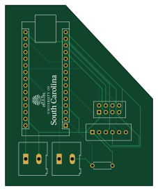
About the Sensor Spike PCB
Sensor Spike is an open source AVR/Arduino PCB design by ARTS-Laboratory, published on GitHub under the CC-BY-SA-4.0 license. It is a 2-layer board measuring 55.9 × 68.6 mm, with 6 components from 6 distinct parts.
Its main chip is the Arduino_Nano_Every, from the AVR/Arduino family. By type, the board carries 2 connectors, 1 module and 1 resistor.
It belongs with the sensors designs in this gallery.
From the project
Design and development of a deployable UAV smart penetrometer
A unique address must be assigned to each node in the thisnode variable in file Arduino/rf24network.ino
0o00 will be the address of the base station. Each node can be labeled 0o01, 0o02, etc...
All known nodes must be declared in the OTHERNODES list. Ex: for 5 nodes connected to base station OTHERNODES = [0o1, 0o2, 0o3, 0o4, 0o5]
*Max of 5 nodes able to connect to nRF24L01+ chip at once.
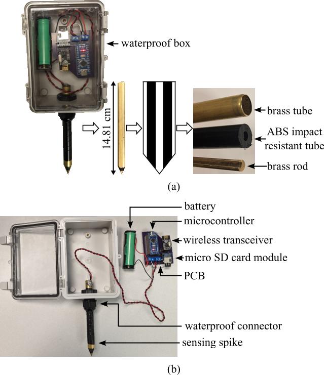
Main components on the Sensor Spike
Sensor Spike bill of materials (BOM)
6 components, 6 distinct parts — part numbers from the project's BOM.
| Qty | Part | Footprint | Refs |
|---|---|---|---|
| 1 | Arduino_Nano_Every | Arduino_Nano | A1 |
| 1 | Power_Input_Screw_Terminal | TerminalBlock_Altech_AK300-2_P5.00mm | J1 |
| 1 | Sensing_Spike_Screw_Terminal | TerminalBlock_Altech_AK300-2_P5.00mm | J2 |
| 1 | ~ | nRF24L01 | RF1 |
| 1 | ~ | SD_Card_Module | SD_CARD1 |
| 1 | 6.8k | R_Axial_DIN0207_L6.3mm_D2.5mm_P7.62mm_Horizontal | R1 |
Sensor Spike design files
The KiCad project lives in the ARTS-Laboratory/Smart-Penetrometer-with-Edge-Computing-and-Intelligent-Embedded-Systems repository on GitHub; these links point at the commit this page was built from.
Sensor Spike: common questions
What microcontroller does the Sensor Spike use?
The Sensor Spike is built around the Arduino_Nano_Every, from the AVR/Arduino family.
How big is the Sensor Spike PCB?
The Sensor Spike measures 55.9 × 68.6 mm, has 2 copper layers and is 1.6 mm thick.
How many components are on the Sensor Spike?
6 components, from 6 distinct parts, with part numbers taken from the project's own BOM. The full bill of materials is listed on this page.
Where can I download the Sensor Spike design files?
From the ARTS-Laboratory/Smart-Penetrometer-with-Edge-Computing-and-Intelligent-Embedded-Systems repository on GitHub, which has the KiCad layout, the schematic and the BOM; the links under Design files point to each one.
Can I use the Sensor Spike design in my own project?
Yes, under the terms of its CC-BY-SA-4.0 license, which ARTS-Laboratory chose for the repository.
Can I test firmware for the Sensor Spike without the hardware?
Yes. HardLabs builds a simulation of the board from its netlist and BOM, so you can run and debug AVR/Arduino firmware against it before you order a PCB.
More boards in Smart-Penetrometer-with-Edge-Computing-and-Intelligent-Embedded-Systems
 AVR/Arduino
Smart penetrometer v0.4.0
33 × 74.9 mm44 parts2LCC-BY-SA-4.06 AVR/Arduino
Smart penetrometer.kicad pro
29 × 93.3 mm32 parts4LCC-BY-SA-4.06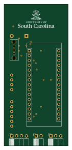 AVR/Arduino
Geophonetdsconductschem2
33 × 73.7 mm22 parts2LCC-BY-SA-4.06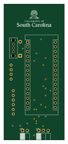 AVR/Arduino
Geophonetdsconductschem
33 × 73.7 mm21 parts2LCC-BY-SA-4.06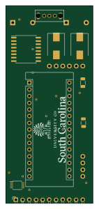 AVR/Arduino
Smart penetrometer
33 × 74.9 mm19 parts2LCC-BY-SA-4.06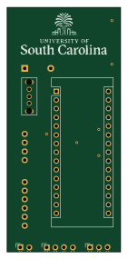 AVR/Arduino
Geophonetdsconductschem3
33 × 71.1 mm14 parts2LCC-BY-SA-4.06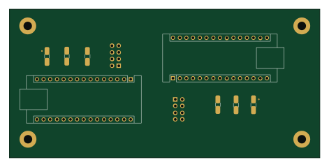 AVR/Arduino
SPECIES receiver
117.6 × 56.1 mm10 parts2LCC-BY-SA-4.06
Similar boards
 AVR/Arduino
Redox keyboard
mattdibi
162.2 × 126.5 mm77 parts2LMIT2.0k AVR/Arduino
ModuleV450
stuartpittaway
30 × 61.4 mm39 parts2LCC-BY-NC-4.01.1k AVR/Arduino
V4
30 × 50 mm38 parts2LCC-BY-NC-4.01.1k AVR/Arduino
Discipline
coseyfannitutti
304.9 × 122.8 mm170 parts2LCC-BY-NC-4.01.0k AVR/Arduino
Megadesk
gcormier
41.7 × 32.2 mm23 parts2LGPL-3.0818 AVR/Arduino
Easyduino Atmega Nano
Hanqaqa
43.4 × 18 mm30 parts4LCERN-OHL-P-2.0746