
6502atty

About the 6502atty PCB
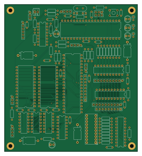
6502atty is an open source AVR/Arduino PCB design by bendooks, published on GitHub under the CERN-OHL-S-2.0 license. It is a 2-layer board measuring 112.5 × 124.5 mm, with 98 components from 32 distinct parts.
Its main chip is the ATMEGA164P-20P, from the AVR/Arduino family. Other key parts include the 74LS112, W65C02SXP, 74LS573, 74HC245 and 27C128. By type, the board carries 43 resistors, 24 capacitors, 12 ICs, 11 connectors, 5 diodes and 1 crystal.
It belongs with the retro computing designs in this gallery.
From the project
6502 SBC with ATMega controller
A 6502 SBC with an ATMega as a contoller and monitor for the 6502.
This is an initial commit as PCBs are off for manufacture and not been tested. This includes the prototype firmware and the first cut of the firmware code.
The firmware is currently in development. To build, you will need at-least avr-gcc and the relevant libraries and is currently only being tested on Linux (Debian). Once built, download to the ATMega using something like avrdude.
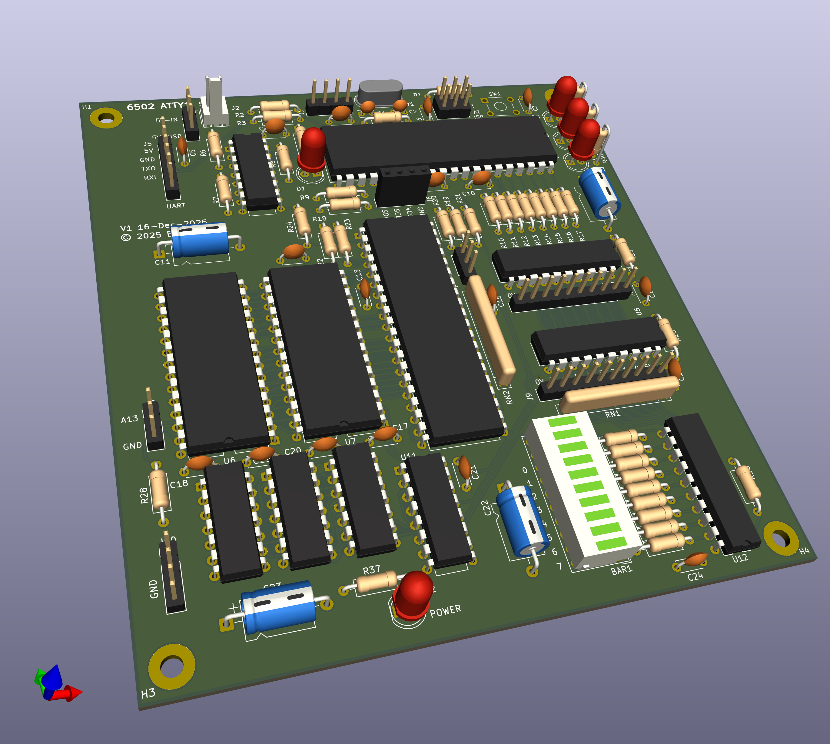
Main components on the 6502atty
6502atty bill of materials (BOM)
98 components, 32 distinct parts — part numbers from the project's BOM.
| Qty | Part | Footprint | Refs |
|---|---|---|---|
| 1 | ATMEGA164P-20P ATmega164P-20P | DIP-40_W15.24mm | U1 |
| 1 | 74LS112 | DIP-16_W7.62mm | U2 |
| 1 | W65C02SXP W65C02SxP | DIP-40_W15.24mm | U3 |
| 2 | 74LS573 | DIP-20_W7.62mm | U4, U12 |
| 1 | 74HC245 | DIP-20_W7.62mm | U5 |
| 1 | 27C128 | DIP-28_W15.24mm | U6 |
| 1 | KM62256CLP | DIP-28_W15.24mm | U7 |
| 2 | 74LS00 | DIP-14_W7.62mm | U8, U9 |
| 1 | 74LS08 | DIP-14_W7.62mm | U10 |
| 1 | 74LS138 | DIP-16_W7.62mm | U11 |
| 1 | 18.341MHZ 18.341MHz | Crystal_HC49-4H_Vertical | Y1 |
| 2 | CONN_01X04_PIN Conn_01x04_Pin | PinHeader_1x04_P2.54mm_Vertical | J1, J10 |
| 1 | CONN_01X02_PIN Conn_01x02_Pin | Molex_KK-254_AE-6410-02A_1x02_P2.54mm_Vertical | J2 |
| 1 | CONN_02X03_ODD_EVEN Conn_02x03_Odd_Even | PinHeader_2x03_P2.54mm_Vertical | J3 |
| 3 | CONN_01X03_PIN Conn_01x03_Pin | PinHeader_1x03_P2.54mm_Vertical | J4, J8, J11 |
| 1 | CONN_01X06_PIN Conn_01x06_Pin | PinHeader_1x06_P2.54mm_Vertical | J5 |
| 1 | CONN_01X04_PIN Conn_01x04_Pin | PinSocket_1x04_P2.54mm_Vertical | J6 |
| 2 | CONN_01X10_PIN Conn_01x10_Pin | PinHeader_1x10_P2.54mm_Vertical | J7, J9 |
| 1 | HDSP-4850 | HDSP-4850 | BAR1 |
| 1 | SW_Push | SW_TH_Tactile_Omron_B3F-10xx | SW1 |
Show 12 more
| Qty | Part | Footprint | Refs |
|---|---|---|---|
| 1 | LED_Small_Filled | LED_D5.0mm | D1 |
| 4 | RED | LED_D5.0mm | D2, D3, D4, D5 |
| 2 | 12PF 12pF | C_Disc_D3.4mm_W2.1mm_P2.50mm | C1, C2 |
| 2 | ~ | C_Disc_D4.3mm_W1.9mm_P5.00mm | C3, C10 |
| 16 | 100NF 100nF | C_Disc_D4.3mm_W1.9mm_P5.00mm | C4, C5, C6, C7, C9, C12, C13, C14 +8 |
| 4 | 100UF/16V 100uF/16V | CP_Axial_L10.0mm_D6.0mm_P15.00mm_Horizontal | C8, C11, C22, C23 |
| 6 | 1K | R_Axial_DIN0207_L6.3mm_D2.5mm_P10.16mm_Horizontal | R1, R2, R3, R4, R5, R37 |
| 13 | R | R_Axial_DIN0207_L6.3mm_D2.5mm_P10.16mm_Horizontal | R6, R7, R8, R19, R20, R21, R22, R23 +5 |
| 2 | 4K7 | R_Axial_DIN0207_L6.3mm_D2.5mm_P10.16mm_Horizontal | R9, R18 |
| 17 | 330R | R_Axial_DIN0207_L6.3mm_D2.5mm_P10.16mm_Horizontal | R10, R11, R12, R13, R14, R15, R16, R17 +9 |
| 3 | 1K | R_Axial_DIN0207_L6.3mm_D2.5mm_P2.54mm_Vertical | R39, R40, R41 |
| 2 | R_NETWORK08 R_Network08 | R_Array_SIP9 | RN1, RN2 |
6502atty design files
The KiCad project lives in the bendooks/6502atty repository on GitHub; these links point at the commit this page was built from.
6502atty: common questions
What microcontroller does the 6502atty use?
The 6502atty is built around the ATMEGA164P-20P, from the AVR/Arduino family.
How big is the 6502atty PCB?
The 6502atty measures 112.5 × 124.5 mm, has 2 copper layers and is 1.6 mm thick.
How many components are on the 6502atty?
98 components, from 32 distinct parts, with part numbers taken from the project's own BOM. The full bill of materials is listed on this page.
Where can I download the 6502atty design files?
From the bendooks/6502atty repository on GitHub, which has the KiCad layout, the schematic and the BOM; the links under Design files point to each one.
Can I use the 6502atty design in my own project?
Yes, under the terms of its CERN-OHL-S-2.0 license, which bendooks chose for the repository.
Can I test firmware for the 6502atty without the hardware?
Yes. HardLabs builds a simulation of the board from its netlist and BOM, so you can run and debug AVR/Arduino firmware against it before you order a PCB.
Similar boards
 AVR/Arduino
Magspoof
samyk
35 × 29 mm11 parts2LNo license4.2k AVR/Arduino
Redox keyboard
mattdibi
162.2 × 126.5 mm77 parts2LMIT2.0k AVR/Arduino
Labrador
espotek-org
36.8 × 34.7 mm75 parts2LNo license1.2k AVR/Arduino
V4
stuartpittaway
30 × 50 mm38 parts2LCC-BY-NC-4.01.1k AVR/Arduino
ModuleV450
30 × 61.4 mm39 parts2LCC-BY-NC-4.01.1k AVR/Arduino
Discipline
coseyfannitutti
304.9 × 122.8 mm170 parts2LCC-BY-NC-4.01.0k