
Gate output

About the Gate output PCB
Gate output is an open source PCB design by carr-james, published on GitHub. It is a 2-layer board, with 6 components from 2 distinct parts.
By type, the board carries 4 diodes and 2 resistors.
It belongs with the audio designs in this gallery.
From the project
Reusable Eurorack circuit blocks (KiCad 10 design blocks) and house design rules
Protects and drives a +5V Eurorack gate or trigger from a CMOS logic output.
The block passes a CMOS logic signal to a jack. R1 limits the current if the output is shorted. D1 and D2 clamp the pin if a patch cable feeds a rail voltage back in.
The block does not amplify, invert, or shape the edge. The output level equals the +5V rail.
A CMOS output drives a Eurorack gate input directly. A gate input is high impedance, near 100k, and triggers near +2.5V.
Gate output bill of materials (BOM)
6 components, 2 distinct parts.
| Qty | Part | Footprint | Refs |
|---|---|---|---|
| 4 | 1N4148 | D_DO-35_SOD27_P7.62mm_Horizontal | D1, D2, D12, D13 |
| 2 | 2k2 | R_Axial_DIN0207_L6.3mm_D2.5mm_P7.62mm_Horizontal | R1, R11 |
Gate output design files
The KiCad project lives in the carr-james/eurorack-blocks repository on GitHub; these links point at the commit this page was built from.
Gate output: common questions
How big is the Gate output PCB?
The Gate output has 2 copper layers and is 1.6 mm thick.
How many components are on the Gate output?
6 components, from 2 distinct parts. The full bill of materials is listed on this page.
Where can I download the Gate output design files?
From the carr-james/eurorack-blocks repository on GitHub, which has the KiCad layout and the schematic; the links under Design files point to each one.
Can I use the Gate output design in my own project?
The repository has no license, so all rights stay with carr-james. Use it as a reference, and ask the author before reusing the design.
More boards in eurorack-blocks
- schematic only · 20 parts
Clock input-3
20 parts2LNo license0 - schematic only · 12 parts
Cv output
12 parts2LNo license0 - schematic only · 12 parts
Cv scale offset
12 parts2LNo license0 - schematic only · 9 parts
Regulator-5v
9 parts2LNo license0 - schematic only · 8 parts
Step counter
8 parts2LNo license0 - schematic only · 8 parts
Cv mux-8
8 parts2LNo license0 - schematic only · 6 parts
Clock input
6 parts2LNo license0 - schematic only · 5 parts
Power input
5 parts2LNo license0 - schematic only · 4 parts
Bus enable
4 parts2LNo license0
Similar boards
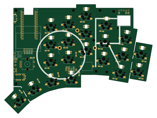
KLOR
GEIGEIGEIST
160.2 × 118.3 mm79 parts2LGPL-3.01.2k
ButtonsLEDs
shanteacontrols
390 × 37 mm82 parts2LApache-2.0956
USB
52 × 12.6 mm6 parts2LApache-2.0956
Pots
390 × 93 mm75 parts2LApache-2.0956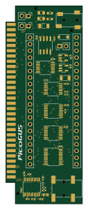
PicoGUS Hand386
polpo
29.2 × 75.2 mm43 parts4LGPL-2.0800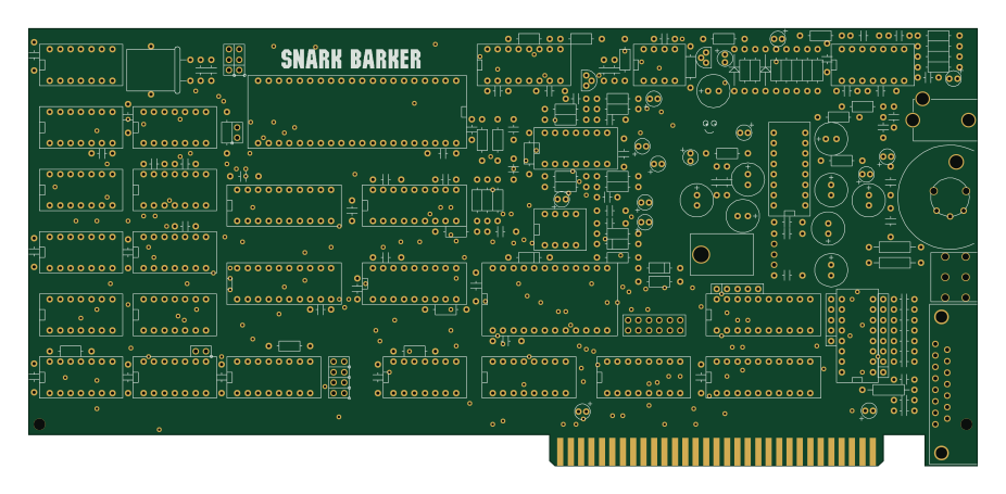
Snark barker
schlae
231.1 × 106.7 mm193 parts2LNo license687