
Probelab

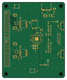
About the Probelab PCB
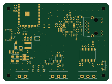
Probelab is an open source RP2040/RP2350 PCB design by enkhbold470, published on GitHub under the CERN-OHL-S-2.0 license. It is a 4-layer board measuring 58 × 70 mm, with 84 components from 32 distinct parts.
Its main chip is the RP2040, from the RP2040/RP2350 family. Other key parts include the W25Q128JVSIQ, USBLC6-2SC6, AP2112K-3.3TRG1, SN74LVC245APWR and USBLC6-4SC6. By type, the board carries 34 resistors, 26 capacitors, 12 ICs, 4 connectors, 4 switches and 3 diodes.
It belongs with the test & measurement and robotics & motion designs in this gallery.
From the project
Five KiCad 10 boards (4- and 6-layer): ESP32-S3 industrial gateway, USB-C PD bench supply, RP2040 logic analyzer, FOC motor controller, iCE40 FPGA board. KiCad projects, gerbers, BOM, STEP, renders and design-process videos.
An RP2040 USB-C logic analyzer: 16 buffered 5 V-tolerant inputs plus two low-speed scope channels.
Not fabricated, assembled or powered. Every number on this page is measured by KiCad 10 on the files in this folder; the full measurements are in report.json.
ProbeLab is a USB-C logic analyzer meant for sigrok/PulseView with sigrok-pico-style RP2040 firmware. It has 16 buffered and clamped logic inputs and two low-speed scope channels into the RP2040's own ADC, on a 58 x 70 mm, 4-layer board.
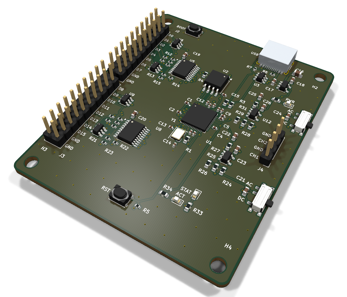
Main components on the Probelab
Probelab bill of materials (BOM)
84 components, 32 distinct parts — part numbers from the project's BOM.
| Qty | Part | Footprint | Refs |
|---|---|---|---|
| 1 | RP2040 | QFN-56-1EP_7x7mm_P0.4mm_EP3.2x3.2mm_ThermalVias | U1 |
| 1 | W25Q128JVSIQ | SOIC-8_5.3x5.3mm_P1.27mm | U2 |
| 1 | USBLC6-2SC6 | SOT-23-6 | U3 |
| 1 | AP2112K-3.3TRG1 AP2112K-3.3 | SOT-23-5 | U4 |
| 2 | SN74LVC245APWR | TSSOP-20_4.4x6.5mm_P0.65mm | U5, U8 |
| 4 | USBLC6-4SC6 | SOT-23-6 | U6, U7, U9, U10 |
| 2 | TLV9061IDBVR | SOT-23-5 | U11, U12 |
| 1 | ABM8-272-T3 12MHz | Crystal_SMD_3225-4Pin_3.2x2.5mm | Y1 |
| 1 | TYPE-C-31-M-12 USB-C | USB_C_Receptacle_HRO_TYPE-C-31-M-12 | J1 |
| 2 | PZ254V-12-20P Conn_02x10 | PinHeader_2x10_P2.54mm_Vertical | J2, J3 |
| 1 | PZ254V-11-04P SCOPE | PinHeader_1x04_P2.54mm_Vertical | J4 |
| 2 | PCM12SMTR | SW_SPDT_PCM12 | SW1, SW2 |
| 1 | PTS810SJM250SMTRLFS BOOTSEL | SW_SPST_PTS810 | SW3 |
| 1 | PTS810SJM250SMTRLFS RESET | SW_SPST_PTS810 | SW4 |
| 1 | KT-0603G Green (PWR) | LED_0603_1608Metric | D1 |
| 1 | KT-0603R Red (STAT) | LED_0603_1608Metric | D2 |
| 1 | KT-0603R Red (ACT) | LED_0603_1608Metric | D3 |
| 11 | CL05B104KO5NNNC 100nF | C_0402_1005Metric | C1, C2, C3, C4, C5, C6, C7, C8 +3 |
| 2 | CL05A105KA5NQNC 1uF | C_0402_1005Metric | C9, C10 |
| 2 | 0402CG150J500NT 15pF | C_0402_1005Metric | C13, C14 |
Show 12 more
| Qty | Part | Footprint | Refs |
|---|---|---|---|
| 1 | CL21A106KAYNNNE 10uF | C_0805_2012Metric | C16 |
| 2 | CL10A105KB8NNNC 1uF | C_0603_1608Metric | C17, C18 |
| 6 | CC0603KRX7R9BB104 100nF | C_0603_1608Metric | C19, C20, C21, C23, C24, C26 |
| 2 | CL10B102KB8NNNC 1nF | C_0603_1608Metric | C22, C25 |
| 5 | 0603WAF1001T5E 1k | R_0603_1608Metric | R1, R4, R32, R33, R34 |
| 2 | 0603WAF270JT5E 27R | R_0603_1608Metric | R2, R3 |
| 1 | 0402WGF1002TCE 10k | R_0402_1005Metric | R5 |
| 2 | 0402WGF5101TCE 5.1k | R_0402_1005Metric | R6, R7 |
| 16 | 0402WGF1000TCE 100R | R_0402_1005Metric | R8, R9, R10, R11, R12, R13, R14, R15 +8 |
| 2 | 0603WAF1004T5E 1M | R_0603_1608Metric | R24, R28 |
| 4 | 0603WAF2203T5E 220k | R_0603_1608Metric | R25, R26, R29, R30 |
| 2 | 0603WAF470JT5E 47R | R_0603_1608Metric | R27, R31 |
Probelab design files
The KiCad project lives in the enkhbold470/kicad-projects repository on GitHub; these links point at the commit this page was built from.
Probelab: common questions
What microcontroller does the Probelab use?
The Probelab is built around the RP2040, from the RP2040/RP2350 family.
How big is the Probelab PCB?
The Probelab measures 58 × 70 mm, has 4 copper layers and is 1.6 mm thick.
How many components are on the Probelab?
84 components, from 32 distinct parts, with part numbers taken from the project's own BOM. The full bill of materials is listed on this page.
Where can I download the Probelab design files?
From the enkhbold470/kicad-projects repository on GitHub, which has the KiCad layout, the schematic and the BOM; the links under Design files point to each one.
Can I use the Probelab design in my own project?
Yes, under the terms of its CERN-OHL-S-2.0 license, which enkhbold470 chose for the repository.
Can I test firmware for the Probelab without the hardware?
Yes. HardLabs builds a simulation of the board from its netlist and BOM, so you can run and debug RP2040/RP2350 firmware against it before you order a PCB.
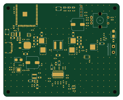
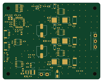
More boards in kicad-projects
Similar boards
 RP2040/RP2350
Open Book Abridged Edition
joeycastillo
85 × 115 mm29 parts2LCC-BY-SA-4.08.1k RP2040/RP2350
Corne
foostan
277.2 × 107.5 mm164 parts2LCC-BY-4.07.7k RP2040/RP2350
Corne
277.2 × 107.5 mm164 parts2LCC-BY-4.07.7k RP2040/RP2350
LogicAnalyzer
gusmanb
57 × 55.2 mm6 parts2LGPL-3.05.0k RP2040/RP2350
Jitx design
55.5 × 65 mm26 parts4LGPL-3.05.0k RP2040/RP2350
Pro V2
kata0510
290.1 × 130 mm270 parts2LMIT2.3k