
Badge

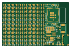
About the Badge PCB
Badge is an open source ESP32 PCB design by glovepost, published on GitHub under the MIT license. It is a 4-layer board measuring 59.3 × 39 mm, with 245 components from 26 distinct parts.
Its main chip is the ESP32-C3-MINI-1-N4, from the ESP32 family. Other key parts include the LSM6DS3TR-C, TPS63020DSJR, ICS-43434, BQ25185DLHR and 532610271. By type, the board carries 118 capacitors, 100 LEDs, 14 resistors, 6 ICs, 2 switches and 1 fuse.
It belongs with the wearables, power & battery and sensors designs in this gallery.
From the project
KiCAD EDA automatic component placement tool
A hackable, battery‑powered LED badge built with Atopile for hardware and PlatformIO/Arduino for firmware. It features a 10×10 SK6805 LED matrix, an ESP32‑C3 module, USB‑C power/data, on‑board charging and regulation, a 6‑axis IMU, an I²S microphone, and a user button. Press the button to cycle through multiple visual/audio‑reactive modes.
- MCU: ESP32-C3-MINI-1 - LEDs: SK6805-EC20 10×10 addressable matrix (100 pixels) - Power: USB‑C, BQ25185 Li‑ion charger + power path, TPS63020 3V3 buck‑boost - Sensors: LSM6DS3 IMU (accel + gyro), ICS‑43434 I²S microphone - I/O: 1x user button, USB‑CDC…
Main components on the Badge
Badge bill of materials (BOM)
245 components, 26 distinct parts.
| Qty | Part | Footprint | Refs |
|---|---|---|---|
| 1 | LSM6DS3TR-C STMicroelectronics | LGA-14_L3.0-W2.5-P0.50-TL | U1 |
| 1 | TPS63020DSJR Texas Instruments | VSON-14_L4.0-W3.0-P0.50-BL-EP_TI_DSJ | U2 |
| 1 | ICS-43434 TDK InvenSense | MIC-SMD_6P-L3.5-W2.7-P0.90-BL | U3 |
| 1 | ESP32-C3-MINI-1-N4 Espressif Systems | WIFIM-SMD_ESP32-C3-MINI-1 | U4 |
| 1 | BQ25185DLHR BQ25185DLHR | WSON-10_L2.2-W2.0-P0.40-BL-EP_TI_DLH0010A | U5 |
| 1 | 532610271 MOLEX | CONN-SMD_532610271 | U6 |
| 1 | — | EEMB_BATTERY_LP402535 | B1 |
| 1 | BSMD0805-050-15V BHFUSE | F0805 | F1 |
| 2 | SKRPACE010 ALPSALPINE | KEY-SMD_4P-L4.2-W3.2-P2.20-LS4.6 | SW1, SW2 |
| 1 | TYPE-C 16PIN 2MD(073) SHOU HAN | USB-C-SMD_TYPE-C-6PIN-2MD-073 | USB1 |
| 100 | SK6805-EC20 OPSCO | LED-SMD_4P-L2.0-W2.0-BR | LED1, LED2, LED3, LED4, LED5, LED6, LED7, LED8 +92 |
| 1 | USBLC6-2SC6 STMicroelectronics | SOT-23-6_L2.9-W1.6-P0.95-LS2.8-BL | D1 |
| 1 | FNR4030S1R0MT 1µH ±20% 4.7A 18mΩ cjiang(Changjiang Microelectronics Tech) | IND-SMD_L4.0-W4.0_FNR40XXS | L1 |
| 108 | CL05B104KO5NNNC 100nF ±10% 16V X7R Samsung Electro-Mechanics | C0402 | C1, C2, C5, C6, C7, C8, C9, C10 +100 |
| 2 | CL21A106KAYNNNE 10µF ±10% 25V X5R Samsung Electro-Mechanics | C0805 | C3, C4 |
| 1 | CL10A226MQ8NRNC 22µF ±20% 6.3V X5R Samsung Electro-Mechanics | C0603 | C108 |
| 4 | CL21A226MQQNNNE 22µF ±20% 6.3V X5R Samsung Electro-Mechanics | C0805 | C110, C111, C112, C116 |
| 2 | CL05A105KA5NQNC 1µF ±10% 25V X5R Samsung Electro-Mechanics | C0402 | C113, C115 |
| 1 | GRM155R60J106ME44D 10µF ±20% 6.3V X5R Murata Electronics | C0402 | C114 |
| 1 | 0402WGF2003TCE 200kΩ ±1% 62.5mW UNI-ROYAL(Uniroyal Elec) | R0402 | R1 |
Show 6 more
| Qty | Part | Footprint | Refs |
|---|---|---|---|
| 2 | 0402WGF1004TCE 1MΩ ±1% 62.5mW UNI-ROYAL(Uniroyal Elec) | R0402 | R2, R3 |
| 5 | 0402WGF1002TCE 10kΩ ±1% 62.5mW UNI-ROYAL(Uniroyal Elec) | R0402 | R4, R7, R8, R11, R15 |
| 1 | 0402WGF1003TCE 100kΩ ±1% 62.5mW UNI-ROYAL(Uniroyal Elec) | R0402 | R5 |
| 2 | 0402WGF5101TCE 5.1kΩ ±1% 62.5mW UNI-ROYAL(Uniroyal Elec) | R0402 | R6, R9 |
| 1 | RC0402FR-0718KL 18kΩ ±1% 62.5mW YAGEO | R0402 | R12 |
| 2 | 0402WGF4701TCE 4.7kΩ ±1% 62.5mW UNI-ROYAL(Uniroyal Elec) | R0402 | R13, R14 |
Badge design files
The KiCad project lives in the glovepost/atoplace repository on GitHub; these links point at the commit this page was built from.
Badge: common questions
What microcontroller does the Badge use?
The Badge is built around the ESP32-C3-MINI-1-N4, from the ESP32 family.
How big is the Badge PCB?
The Badge measures 59.3 × 39 mm, has 4 copper layers and is 1.6 mm thick.
How many components are on the Badge?
245 components, from 26 distinct parts. The full bill of materials is listed on this page.
Where can I download the Badge design files?
From the glovepost/atoplace repository on GitHub, which has the KiCad layout; the links under Design files point to each one.
Can I use the Badge design in my own project?
Yes, under the terms of its MIT license, which glovepost chose for the repository.
Can I test firmware for the Badge without the hardware?
Yes. HardLabs builds a simulation of the board from its netlist and BOM, so you can run and debug ESP32 firmware against it before you order a PCB.
More boards in atoplace
 RP2040/RP2350
Demomatrix
10.8 × 7.4 mm1591 parts2LMIT1
Demo matrix2
116.2 × 116.2 mm496 parts2LMIT1
Grid100x100
33.6 × 35.5 mm200 parts4LMIT1
Default
45 × 167 mm137 parts4LMIT1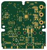
Servo drive
37.6 × 39.9 mm119 parts4LMIT1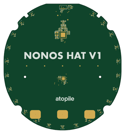
Hat
108 × 115.8 mm83 parts4LMIT1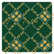
Cluster test
26.2 × 26.2 mm31 parts2LMIT1
Cluster2x2
26.2 × 26.2 mm31 parts2LMIT1
Strip10
33.6 × 2 mm20 parts2LMIT1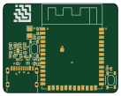 ESP32
ESP32Esp32 minimal
34.2 × 26.8 mm19 parts2LMIT1
Row2
26.2 × 11.2 mm10 parts2LMIT1
Similar boards
 ESP32
ESP32Open Book Abridged Edition
joeycastillo
85 × 115 mm65 parts2LCC-BY-SA-4.08.1k ESP32
ESP32Badge
atopile
56.3 × 39 mm239 parts4LMIT4.0k ESP32
ESP32Esp32 minimal
36.2 × 26.8 mm20 parts2LMIT4.0k ESP32
ESP32Racer
StuckAtPrototype
36 × 50.2 mm70 parts4LApache-2.03.8k ESP32
ESP32Controller
29 × 74 mm58 parts4LApache-2.03.8k ESP32
ESP32Bitaxe
skot
56.5 × 99.8 mm86 parts4LCERN-OHL-S-2.01.4k