
Charger

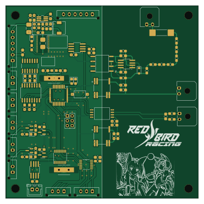
About the Charger PCB
Charger is an open source AVR/Arduino PCB design by HKUST-Red-Bird-Racing-EVRT, published on GitHub. It is a 2-layer board measuring 100 × 100 mm, with 126 components from 72 distinct parts.
Its main chip is the BQ76940DBT, from the AVR/Arduino family. Other key parts include the ATMEGA328P-A, MCP2515-XST, ISO1050DUB, AD5235BRUZ25 and TPS54302. By type, the board carries 43 resistors, 36 capacitors, 14 connectors, 13 ICs, 6 diodes and 4 transistors.
It belongs with the power & battery designs in this gallery.
From the project
ELEC Github Repo for Gen 6
Main components on the Charger
Charger bill of materials (BOM)
126 components, 72 distinct parts — part numbers from the project's BOM.
| Qty | Part | Footprint | Refs |
|---|---|---|---|
| 1 | BQ76940DBT ATmega328-A | TQFP-32_7x7mm_P0.8mm_L | U1 |
| 1 | ATMEGA328P-A MCP2515-xST | TSSOP-20_4.4x6.5mm_P0.65mm | U2 |
| 1 | MCP2515-XST TJA1050T_CM_118 | SOIC-8_3.9x4.9mm_P1.27mm_RMC_Handsolder | U3 |
| 1 | ISO1050DUB TPS54302 | SOT-23-6_Handsoldering_Extended_RMC | U4 |
| 1 | AD5235BRUZ25 | SOP65P640X120-16N | U5 |
| 1 | TPS54302 40106 | SOIC127P600X175-14N | U6 |
| 1 | LTV-847S | SOIC-16W_5.3x10.2mm_P1.27mm_betterHandSolder | U7 |
| 2 | LM358 | SOIC-8_3.9x4.9mm_P1.27mm_RMC_Handsolder | U8, U13 |
| 2 | ~ | B0505MT-1WR4 | U9, U11 |
| 1 | AMC1302QDWVQ1 | DWV8_TEX | U10 |
| 1 | ~ | LOC110P | U12 |
| 1 | KY2N7002 MMBT3906 | SOT-23 | Q1 |
| 1 | AO3402 AO3400A | SOT-23 | Q2 |
| 1 | NCE60P04Y MMBT3906 | SOT-23 | Q3 |
| 1 | AO3400A | SOT-23 | Q4 |
| 1 | 20MHZ 20MHz | Crystal_HC49-U_Vertical_W_SMD | Y1 |
| 1 | 8MHZ 20MHz | Crystal_HC49-U_Vertical_W_SMD | Y2 |
| 1 | CONN_01X05 Conn_01x03 | Molex_Micro-Fit_3.0_43650-0315_1x03_P3.00mm_Vertical | J4 |
| 1 | Conn_01x03 | Molex_Micro-Fit_3.0_43650-0315_1x03_P3.00mm_Vertical | J5 |
| 5 | Conn_01x02 | Molex_Micro-Fit_3.0_43650-0215_1x02_P3.00mm_Vertical | J6, J13, J14, J15, J16 |
Show 52 more
| Qty | Part | Footprint | Refs |
|---|---|---|---|
| 3 | Conn_01x02 | Molex_Micro-Fit_3.0_43650-0200_1x02_P3.00mm_Horizontal | J7, J11, J12 |
| 1 | AVR-ISP-6 | PinHeader_2x03_P2.54mm_Vertical | J8 |
| 2 | Conn_01x06 | Molex_Micro-Fit_3.0_43650-0615_1x06_P3.00mm_Vertical | J9, J10 |
| 1 | Conn_01x02 | JST_XH_B2B-XH-A_1x02_P2.50mm_Vertical | J17 |
| 4 | 100nF | C_0805_2012Metric_Pad1.18x1.45mm_HandSolder_L | CA1, CA2, CA3, CA5 |
| 1 | Fuse | Fuse_1210_3225Metric_Pad1.42x2.65mm_HandSolder | F1 |
| 1 | Fuse | LittleFuse_462 | F2 |
| 1 | SW_Push | SW_SPST_CK_RS282G05A3 | SW2 |
| 2 | 1N4148W LED | LED_0805_2012Metric_Pad1.45x1.40mm_HandSolder | D2, D3 |
| 3 | LED | LED_0805_2012Metric_Pad1.45x1.40mm_HandSolder | D9, D10, D13 |
| 1 | BZT52B5V1 | D_SOD-123F | D11 |
| 1 | 6.8UH 10uH | L_6.3x6.3_H3 | L1 |
| 6 | 1UF 100nF | C_0805_2012Metric_Pad1.18x1.45mm_HandSolder_L | C1, C2, C3, C10, C11, C14 |
| 3 | 1UF 10uF | C_0805_2012Metric_Pad1.18x1.45mm_HandSolder_L | C4, C7, C13 |
| 4 | 1UF 12pF | C_0805_2012Metric_Pad1.18x1.45mm_HandSolder_L | C5, C6, C8, C9 |
| 1 | 1UF 47uF | C_1210_3225Metric_Pad1.33x2.70mm_HandSolder | C12 |
| 5 | 100NF 100nF | C_0805_2012Metric_Pad1.18x1.45mm_HandSolder_L | C15, C23, C25, C27, C34 |
| 1 | 4.7UF 22uF | C_0805_2012Metric_Pad1.18x1.45mm_HandSolder_L | C16 |
| 1 | 1UF 22uF | C_0805_2012Metric_Pad1.18x1.45mm_HandSolder_L | C17 |
| 2 | 12PF 100nF | C_0805_2012Metric_Pad1.18x1.45mm_HandSolder_L | C18, C19 |
| 2 | 100NF 1uF | C_0805_2012Metric_Pad1.18x1.45mm_HandSolder_L | C20, C33 |
| 2 | 100NF 10uF/25V | C_0805_2012Metric_Pad1.18x1.45mm_HandSolder_L | C21, C22 |
| 3 | 10UF 100nF | C_0805_2012Metric_Pad1.18x1.45mm_HandSolder_L | C24, C30, C35 |
| 1 | 100NF 10nF | C_0805_2012Metric_Pad1.18x1.45mm_HandSolder_L | C26 |
| 2 | 22PF 100nF | C_0805_2012Metric_Pad1.18x1.45mm_HandSolder_L | C28, C29 |
| 2 | 4.7UF 10uF/25V | C_0805_2012Metric_Pad1.18x1.45mm_HandSolder_L | C31, C32 |
| 1 | 22UF 100nF | C_0805_2012Metric_Pad1.18x1.45mm_HandSolder_L | C36 |
| 2 | 10M | R_0805_2012Metric_Pad1.20x1.40mm_HandSolder_L | R2, R6 |
| 4 | 1k | R_0805_2012Metric_Pad1.20x1.40mm_HandSolder_L | R3, R12, R13, R43 |
| 1 | 4.7k | R_0805_2012Metric_Pad1.20x1.40mm_HandSolder_L | R4 |
| 3 | 10k | R_0805_2012Metric_Pad1.20x1.40mm_HandSolder_L | R5, R7, R48 |
| 1 | 120 | R_0805_2012Metric_Pad1.20x1.40mm_HandSolder_L | R8 |
| 1 | 49R9 | R_0805_2012Metric_Pad1.20x1.40mm_HandSolder_L | R9 |
| 2 | 100k | R_0805_2012Metric_Pad1.20x1.40mm_HandSolder_L | R10, R14 |
| 1 | 13k3 | R_0805_2012Metric_Pad1.20x1.40mm_HandSolder_L | R11 |
| 1 | 500K 1k | R_0805_2012Metric_Pad1.20x1.40mm_HandSolder_L | R15 |
| 1 | 10M 1k | R_0805_2012Metric_Pad1.20x1.40mm_HandSolder_L | R16 |
| 5 | 10K 1k | R_0805_2012Metric_Pad1.20x1.40mm_HandSolder_L | R17, R19, R28, R29, R30 |
| 1 | 4.7K 100k | R_0805_2012Metric_Pad1.20x1.40mm_HandSolder_L | R18 |
| 2 | 4.7K 1k | R_0805_2012Metric_Pad1.20x1.40mm_HandSolder_L | R20, R22 |
| 1 | 120R 1k | R_0805_2012Metric_Pad1.20x1.40mm_HandSolder_L | R21 |
| 2 | 10K 10k | R_0805_2012Metric_Pad1.20x1.40mm_HandSolder_L | R24, R26 |
| 1 | 174K 10k | R_0805_2012Metric_Pad1.20x1.40mm_HandSolder_L | R25 |
| 3 | 10K 4.7k | R_0805_2012Metric_Pad1.20x1.40mm_HandSolder_L | R32, R33, R34 |
| 1 | 10K 210k | R_0805_2012Metric_Pad1.20x1.40mm_HandSolder_L | R36 |
| 2 | 100K 210k | R_0805_2012Metric_Pad1.20x1.40mm_HandSolder_L | R37, R41 |
| 1 | 22.1K 210k | R_0805_2012Metric_Pad1.20x1.40mm_HandSolder_L | R38 |
| 1 | 511K 210k | R_0805_2012Metric_Pad1.20x1.40mm_HandSolder_L | R39 |
| 1 | 105K 210k | R_0805_2012Metric_Pad1.20x1.40mm_HandSolder_L | R40 |
| 1 | 301K 10k | R_0805_2012Metric_Pad1.20x1.40mm_HandSolder_L | R42 |
| 2 | 10R | R_0805_2012Metric_Pad1.20x1.40mm_HandSolder_L | R44, R45 |
| 2 | 100k/1% | R_0805_2012Metric_Pad1.20x1.40mm_HandSolder_L | R46, R47 |
Charger design files
The KiCad project lives in the HKUST-Red-Bird-Racing-EVRT/GEN6_ELEC repository on GitHub; these links point at the commit this page was built from.
Charger: common questions
What microcontroller does the Charger use?
The Charger is built around the BQ76940DBT, from the AVR/Arduino family.
How big is the Charger PCB?
The Charger measures 100 × 100 mm, has 2 copper layers and is 1.6 mm thick.
How many components are on the Charger?
126 components, from 72 distinct parts, with part numbers taken from the project's own BOM. The full bill of materials is listed on this page.
Where can I download the Charger design files?
From the HKUST-Red-Bird-Racing-EVRT/GEN6_ELEC repository on GitHub, which has the KiCad layout, the schematic and the BOM; the links under Design files point to each one.
Can I use the Charger design in my own project?
The repository has no license, so all rights stay with HKUST-Red-Bird-Racing-EVRT. Use it as a reference, and ask the author before reusing the design.
Can I test firmware for the Charger without the hardware?
Yes. HardLabs builds a simulation of the board from its netlist and BOM, so you can run and debug AVR/Arduino firmware against it before you order a PCB.
More boards in GEN6_ELEC
 AVR/Arduino
AMS SLAVE TEST
68 × 110 mm191 parts2LNo license0 AVR/Arduino
AMS slave
68 × 110 mm189 parts2LNo license0 AVR/Arduino
BDUCU
140 × 60 mm169 parts2LNo license0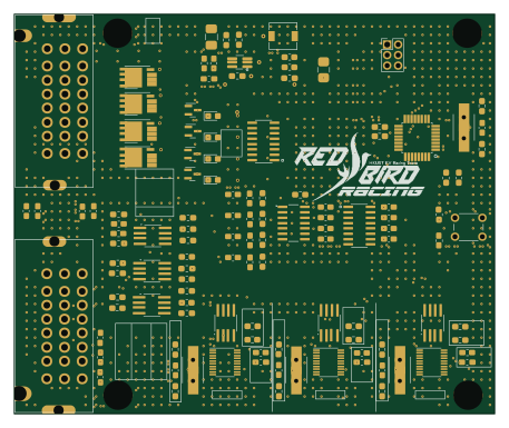 AVR/Arduino
VCU V3.3
114 × 95 mm145 parts2LNo license0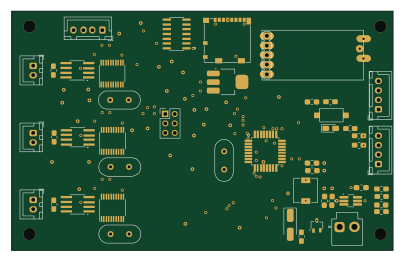 AVR/Arduino
Front dash unit
101 × 63.3 mm90 parts2LNo license0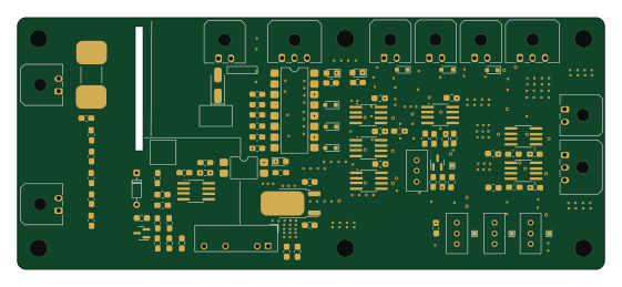 AVR/Arduino
TSALG ACCUM V2
140 × 60 mm88 parts2LNo license0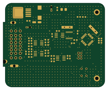 AVR/Arduino
SSRU v4.0
95 × 78 mm68 parts2LNo license0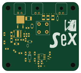 AVR/Arduino
Gen 6 ts indicator v1.0
66.8 × 60 mm46 parts2LNo license0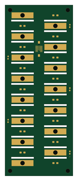
VTAP
68 × 171.5 mm36 parts2LNo license0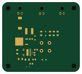 AVR/Arduino
600 to 12V dc
66.8 × 60 mm26 parts2LNo license0
Similar boards
 AVR/Arduino
Redox keyboard
mattdibi
162.2 × 126.5 mm77 parts2LMIT2.0k AVR/Arduino
ModuleV450
stuartpittaway
30 × 61.4 mm39 parts2LCC-BY-NC-4.01.1k AVR/Arduino
V4
30 × 50 mm38 parts2LCC-BY-NC-4.01.1k AVR/Arduino
Discipline
coseyfannitutti
304.9 × 122.8 mm170 parts2LCC-BY-NC-4.01.0k AVR/Arduino
Megadesk
gcormier
41.7 × 32.2 mm23 parts2LGPL-3.0818 AVR/Arduino
Easyduino Atmega Nano
Hanqaqa
43.4 × 18 mm30 parts4LCERN-OHL-P-2.0746