
Rp2040plus devboard

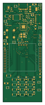
About the Rp2040plus devboard PCB
Rp2040plus devboard is an open source RP2040/RP2350 PCB design by joshujo, published on GitHub. It is a 4-layer board measuring 40 × 100 mm, with 98 components from 33 distinct parts.
Its main chip is the RP2040, from the RP2040/RP2350 family. Other key parts include the NCP1117-3.3_SOT223, W25Q128JVS, HS96L03W2C03, TPS2116DRL and MLT-8530. By type, the board carries 25 diodes, 25 capacitors, 19 resistors, 15 switches, 7 ICs and 5 connectors.
It belongs with the sensors, dev boards & breakouts and displays & leds designs in this gallery.
From the project
This is a devboard that is designed to have a basic sensor, OLED screen, buttons and LEDs pre-embedded onto the board. The idea of this design was to have some basic hardware already available on the develepment board itself so an external bread board and some additional componen
This is a devboard that is designed to have a basic sensor, OLED screen, buttons and LEDs pre-embedded onto the board. The idea of this design was to have some basic hardware already available on the develepment board itself so an external bread board and some additional components with a kit and such is not needed to use it. Additionally, it can be used as a simple console or just a temperature monitor if desired. The board is designed to be extended with an additional 17 GPIO pins exposed to the user for prototyping.
Main components on the Rp2040plus devboard
Rp2040plus devboard bill of materials (BOM)
98 components, 33 distinct parts — part numbers from the project's BOM.
| Qty | Part | Footprint | Refs |
|---|---|---|---|
| 1 | RP2040 | QFN-56-1EP_7x7mm_P0.4mm_EP3.2x3.2mm | U1 |
| 1 | NCP1117-3.3_SOT223 | SOT-223-3_TabPin2 | U2 |
| 1 | W25Q128JVS | SOIC-8_5.3x5.3mm_P1.27mm | U3 |
| 1 | HS96L03W2C03 | HS96L03W2C03 | U4 |
| 1 | TPS2116DRL | SOT-583-8 | U5 |
| 1 | MLT-8530 | MLT-8530 | U7 |
| 1 | HDC1080 | Texas_S-PWSON-N6-HDC2080 | U8 |
| 1 | BSS138 | SOT-23 | Q1 |
| 1 | NDK NX3225GA-12MHZ-STD-CRG-2 | Crystal_SMD_3225-4Pin_3.2x2.5mm_HandSoldering | Y1 |
| 1 | USB_C_RECEPTACLE_USB2.0_14P USB_C_Receptacle_USB2.0_14P | USB_C_Receptacle_G-Switch_GT-USB-7010ASV | J1 |
| 1 | USB_C_RECEPTACLE_POWERONLY_6P USB_C_Receptacle_PowerOnly_6P | USB_C_Receptacle_GCT_USB4125-xx-x_6P_TopMnt_Horizontal | J2 |
| 2 | CONN_01X10_PIN Conn_01x10_Pin | PinHeader_1x10_P2.54mm_Vertical | J3, J4 |
| 1 | CONN_01X03_PIN Conn_01x03_Pin | PinHeader_1x03_P2.54mm_Vertical | J5 |
| 15 | SW_Push | SW_Push_SPST_NO_Alps_SKRK | SW1, SW2, SW3, SW4, SW5, SW6, SW7, SW8 +7 |
| 2 | KT-0805G | LED_0805_2012Metric_Pad1.15x1.40mm_HandSolder | D1, D2 |
| 13 | CD4148W | D_0805_2012Metric_Pad1.15x1.40mm_HandSolder | D3, D4, D5, D6, D7, D8, D9, D10 +5 |
| 10 | WS2812B-2020 | LED_WS2812B-2020_PLCC4_2.0x2.0mm | D16, D17, D18, D19, D20, D21, D22, D23 +2 |
| 2 | 1u | C_0402_1005Metric | C1, C10 |
| 10 | 100N 100n | C_0402_1005Metric | C2, C3, C4, C5, C6, C7, C8, C9 +2 |
| 2 | 10U 10u | C_0603_1608Metric_Pad1.08x0.95mm_HandSolder | C13, C14 |
Show 13 more
| Qty | Part | Footprint | Refs |
|---|---|---|---|
| 3 | 100N 100n | C_0603_1608Metric_Pad1.08x0.95mm_HandSolder | C15, C18, C19 |
| 2 | 33P 33p | C_0603_1608Metric_Pad1.08x0.95mm_HandSolder | C16, C17 |
| 1 | 1u | C_0603_1608Metric_Pad1.08x0.95mm_HandSolder | C20 |
| 5 | 100U 100u | C_1206_3216Metric_Pad1.33x1.80mm_HandSolder | C21, C22, C23, C24, C25 |
| 2 | 27.4 | R_0603_1608Metric_Pad0.98x0.95mm_HandSolder | R1, R2 |
| 4 | 5.1K | R_0603_1608Metric_Pad0.98x0.95mm_HandSolder | R3, R4, R5, R6 |
| 2 | 10K 10k | R_0603_1608Metric_Pad0.98x0.95mm_HandSolder | R7, R9 |
| 1 | 33K 33k | R_0603_1608Metric_Pad0.98x0.95mm_HandSolder | R8 |
| 1 | 1k | R_0603_1608Metric_Pad0.98x0.95mm_HandSolder | R10 |
| 1 | 1k | R_0402_1005Metric | R11 |
| 3 | 470 | R_0603_1608Metric_Pad0.98x0.95mm_HandSolder | R12, R18, R19 |
| 4 | 5k | R_0603_1608Metric_Pad0.98x0.95mm_HandSolder | R13, R14, R15, R16 |
| 1 | 100 | R_0603_1608Metric_Pad0.98x0.95mm_HandSolder | R17 |
Rp2040plus devboard design files
The KiCad project lives in the joshujo/rp2040plus-devboard repository on GitHub; these links point at the commit this page was built from.
Rp2040plus devboard: common questions
What microcontroller does the Rp2040plus devboard use?
The Rp2040plus devboard is built around the RP2040, from the RP2040/RP2350 family.
How big is the Rp2040plus devboard PCB?
The Rp2040plus devboard measures 40 × 100 mm, has 4 copper layers and is 1.6 mm thick.
How many components are on the Rp2040plus devboard?
98 components, from 33 distinct parts, with part numbers taken from the project's own BOM. The full bill of materials is listed on this page.
Where can I download the Rp2040plus devboard design files?
From the joshujo/rp2040plus-devboard repository on GitHub, which has the KiCad layout, the schematic and the BOM; the links under Design files point to each one.
Can I use the Rp2040plus devboard design in my own project?
The repository has no license, so all rights stay with joshujo. Use it as a reference, and ask the author before reusing the design.
Can I test firmware for the Rp2040plus devboard without the hardware?
Yes. HardLabs builds a simulation of the board from its netlist and BOM, so you can run and debug RP2040/RP2350 firmware against it before you order a PCB.
Similar boards
 RP2040/RP2350
Open Book Abridged Edition
joeycastillo
85 × 115 mm29 parts2LCC-BY-SA-4.08.1k RP2040/RP2350
Corne
foostan
277.2 × 107.5 mm164 parts2LCC-BY-4.07.7k RP2040/RP2350
Corne
277.2 × 107.5 mm164 parts2LCC-BY-4.07.7k RP2040/RP2350
Jitx design
gusmanb
55.5 × 65 mm26 parts4LGPL-3.05.0k RP2040/RP2350
LogicAnalyzer
57 × 55.2 mm6 parts2LGPL-3.05.0k RP2040/RP2350
Main
google
98 × 71 mm102 parts2LApache-2.02.9k