
Gps logger

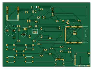
About the Gps logger PCB
Gps logger is an open source ESP32 PCB design by kaushalch1, published on GitHub. It is a 2-layer board measuring 96.5 × 71 mm, with 47 components from 29 distinct parts.
Its main chip is the ESP32-S3-WROOM-1-N16R8, from the ESP32 family. Other key parts include the BQ24074RGT, AP2112K-3.3, USBLC6-2SC6, NEO-M9N and ER_OLEDM0.91_1x-I2C. By type, the board carries 14 resistors, 12 capacitors, 7 ICs, 5 switches, 3 connectors and 2 diodes.
It belongs with the rf & radio, iot & wireless and power & battery designs in this gallery.
From the project
this is a gps device designed to record and track journeys without depending on a phone or a constant bluetooth connection.the idea behind this project is to make it easier to collect travel and movement data while hiking or cycling or exploring new places.
this is a gps device designed to record and track journeys without depending on a phone or a constant bluetooth connection.the idea behind this project is to make it easier to collect travel and movement data while hiking or cycling or exploring new places.
the device uses an esp-s3 as its main controller, along with a gps receiver and an oled display, a motion sensor, and a microsd card for storing data. it records information locally so that it can be accessed later, even without an internet connection.
Main components on the Gps logger
Gps logger bill of materials (BOM)
47 components, 29 distinct parts.
| Qty | Part | Footprint | Refs |
|---|---|---|---|
| 1 | ESP32-S3-WROOM-1-N16R8 ESP32-S3-WROOM-1 ESPRESSIF(乐鑫) | WIRELM-SMD_ESP32-S3-WROOM-1 | U1 |
| 1 | BQ24074RGT | VQFN-16-1EP_3x3mm_P0.5mm_EP1.6x1.6mm | U2 |
| 1 | AP2112K-3.3 | SOT-23-5 | U3 |
| 1 | USBLC6-2SC6 | SOT-23-6 | U4 |
| 1 | NEO-M9N | ublox_NEO | U5 |
| 1 | ER_OLEDM0.91_1x-I2C | ER_OLEDM0.91_1x-I2C | U6 |
| 1 | BMI270 Bosch(博世) | LGA-14_L3.0-W2.5-P0.50-BR | U7 |
| 1 | 2N3904 | TO-92_Inline | Q1 |
| 1 | USB_C_Receptacle_USB2.0_16P | USB_C_Receptacle_HRO_TYPE-C-31-M-12 | J1 |
| 1 | Micro_SD_Card | microSD_HC_Hirose_DM3AT-SF-PEJM5 | J3 |
| 1 | Conn_01x02_Pin | JST_PH_B2B-PH-K_1x02_P2.00mm_Vertical | J4 |
| 1 | Buzzer | Buzzer_12x9.5RM7.6 | BZ1 |
| 1 | U.FL-R-SMT-1(10) U.FL-R-SMT-1 HRS(广濑) | ANT-SMD_UFL-R-SMT-1-10 | JP1 |
| 5 | SW_Push | SW_SPST_PTS645Sx43SMTR92 | SW1, SW2, SW3, SW4, SW5 |
| 1 | 1N4148 | D_DO-35_SOD27_P7.62mm_Horizontal | D1 |
| 1 | LED | LED_0805_2012Metric | D2 |
| 1 | 27nH | L_0805_2012Metric | L1 |
| 6 | 10uF | C_0805_2012Metric | C1, C3, C4, C5, C6, C8 |
| 1 | 1uF | C_0805_2012Metric | C2 |
| 4 | 100nF | C_0805_2012Metric | C7, C10, C11, C12 |
Show 9 more
| Qty | Part | Footprint | Refs |
|---|---|---|---|
| 1 | 47pF | C_0805_2012Metric | C9 |
| 3 | 10k | R_0805_2012Metric | R1, R4, R12 |
| 2 | 5k | R_0805_2012Metric | R2, R3 |
| 1 | 1.5k | R_0805_2012Metric | R5 |
| 1 | 1.8k | R_0805_2012Metric | R6 |
| 2 | 100k | R_0805_2012Metric | R7, R8 |
| 1 | 2.1k | R_0805_2012Metric | R9 |
| 2 | 4.7k | R_0805_2012Metric | R10, R11 |
| 2 | 1k | R_0805_2012Metric | R13, R14 |
Gps logger design files
The KiCad project lives in the kaushalch1/gps-logger repository on GitHub; these links point at the commit this page was built from.
Gps logger: common questions
What microcontroller does the Gps logger use?
The Gps logger is built around the ESP32-S3-WROOM-1-N16R8, from the ESP32 family.
How big is the Gps logger PCB?
The Gps logger measures 96.5 × 71 mm, has 2 copper layers and is 1.6 mm thick.
How many components are on the Gps logger?
47 components, from 29 distinct parts. The full bill of materials is listed on this page.
Where can I download the Gps logger design files?
From the kaushalch1/gps-logger repository on GitHub, which has the KiCad layout and the schematic; the links under Design files point to each one.
Can I use the Gps logger design in my own project?
The repository has no license, so all rights stay with kaushalch1. Use it as a reference, and ask the author before reusing the design.
Can I test firmware for the Gps logger without the hardware?
Yes. HardLabs builds a simulation of the board from its netlist and BOM, so you can run and debug ESP32 firmware against it before you order a PCB.
Similar boards
 ESP32
OSO-BOOK-B1
joeycastillo
85 × 115 mm65 parts2LCC-BY-SA-4.08.1k ESP32
Powertrain
byrantech
64 × 45.4 mm171 parts4LMIT4.3k ESP32
Badge
atopile
56.3 × 39 mm239 parts4LMIT4.0k ESP32
Esp32 minimal
36.2 × 26.8 mm20 parts2LMIT4.0k ESP32
Controller
StuckAtPrototype
29 × 74 mm58 parts4LApache-2.03.8k ESP32
Racer
36 × 50.2 mm70 parts4LApache-2.03.8k