
ECE3502 PCB Design Course - Motor Driver Project

About the ECE3502 PCB Design Course - Motor Driver Project
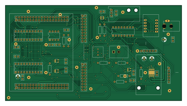
ECE3502 PCB Design Course - Motor Driver Project is an open source PCB design by MilesMayhew, published on GitHub. It is a 2-layer board measuring 158.2 × 86 mm, with 48 components from 30 distinct parts.
Other key parts include the 74S374, LTD-4708JR, GP2Y0A21YK0F, DRV8833PWP and NE555P. By type, the board carries 18 capacitors, 11 resistors, 10 ICs, 7 connectors and 1 switch.
It belongs with the robotics & motion designs in this gallery.
From the project
This board is designed to be used in a classroom setting and expands available I/O devices for both the STM32 and TI MSPM0 development boards. It is powered by a 12V DC Barrel jack which is then used to create a 5V and a 3.3V rail. The board can supply power to both the STM32 and
This board is designed to be used in a classroom setting and expands available I/O devices for both the STM32 and TI MSPM0 development boards. It is powered by a 12V DC Barrel jack which is then used to create a 5V and a 3.3V rail. The board can supply power to both the STM32 and TI MSPM0 through the U1 and U4 header pins. It expands the available I/O to 9 major devices: DC servo motor, buzzer, additional buttons, joystick, microphone, light sensor, RGB LED, LCD screen, and NUM-pad.
Main components on the ECE3502 PCB Design Course - Motor Driver Project
ECE3502 PCB Design Course - Motor Driver Project bill of materials (BOM)
48 components, 30 distinct parts.
| Qty | Part | Footprint | Refs |
|---|---|---|---|
| 2 | 74S374 | DIP-20_W7.62mm_Socket | U1, U5 |
| 1 | LTD-4708JR | 7SegmentLED_LTD-4708JR | U2 |
| 1 | GP2Y0A21YK0F | PinHeader_1x03_P2.54mm_Vertical | U3 |
| 1 | DRV8833PWP | HTSSOP-16-1EP_4.4x5mm_P0.65mm_EP3.4x5mm_Mask2.46x2.31mm_ThermalVias | U4 |
| 1 | NE555P | DIP-8_W7.62mm | U6 |
| 1 | 74LVC1GU04DRL | SOT-23-5_HandSoldering | U7 |
| 1 | 74LVC1G07 | SOT-23-5_HandSoldering | U8 |
| 1 | 74LVC2G17 | SOT-23-6 | U9 |
| 1 | 74LVC1G17 | SOT-23-5 | U10 |
| 1 | Conn_2Rows-38Pins_CN7 | PinSocket_2x19_P2.54mm_Vertical_CN7 | CN7 |
| 1 | Conn_2Rows-38Pins_CN10 | PinSocket_2x19_P2.54mm_Vertical_CN10 | CN10 |
| 1 | Conn_Coaxial_3_Pin | BarrelJack_GCT_DCJ200-10-A_Horizontal | J1 |
| 1 | Test Points | PinHeader_2x10_P2.54mm_Vertical | J2 |
| 1 | Display Test Points | PinHeader_2x10_P2.54mm_Vertical | J3 |
| 2 | ~ | PinHeader_1x06_P2.54mm_Vertical | J4, J10 |
| 1 | 10K | TRIM_COM-09806 | RV1 |
| 1 | SW_SPST | SW2_GF-123-0054_CWI | SW1 |
| 3 | 10UF | CP_Radial_D4.0mm_P1.50mm | C1, C11, C13 |
| 1 | 2.2uF | CP_Radial_D4.0mm_P1.50mm | C2 |
| 1 | 0.01 uF | C_Disc_D5.0mm_W2.5mm_P2.50mm | C3 |
Show 10 more
| Qty | Part | Footprint | Refs |
|---|---|---|---|
| 10 | 0.1uF | C_Disc_D5.0mm_W2.5mm_P2.50mm | C4, C5, C6, C7, C9, C10, C12, C14 +2 |
| 1 | 0.47 | C_Disc_D5.0mm_W2.5mm_P2.50mm | C8 |
| 1 | 0.01uF | C_Disc_D5.0mm_W2.5mm_P2.50mm | C15 |
| 1 | 0.47uF | C_Disc_D5.0mm_W2.5mm_P2.50mm | C18 |
| 6 | 10K | R_Axial_DIN0207_L6.3mm_D2.5mm_P10.16mm_Horizontal | R1, R2, R10, R13, R15, R16 |
| 1 | 4.7K | R_Axial_DIN0207_L6.3mm_D2.5mm_P10.16mm_Horizontal | R9 |
| 1 | 33K | R_Axial_DIN0207_L6.3mm_D2.5mm_P10.16mm_Horizontal | R11 |
| 1 | 27K | R_Axial_DIN0207_L6.3mm_D2.5mm_P10.16mm_Horizontal | R12 |
| 1 | 1K | R_Axial_DIN0207_L6.3mm_D2.5mm_P10.16mm_Horizontal | R14 |
| 1 | R_Pack08_Split | DIP-16_W7.62mm | RN1 |
ECE3502 PCB Design Course - Motor Driver Project design files
The KiCad project lives in the MilesMayhew/Pedagogical-PCB repository on GitHub; these links point at the commit this page was built from.
ECE3502 PCB Design Course - Motor Driver Project: common questions
How big is the ECE3502 PCB Design Course - Motor Driver Project?
The ECE3502 PCB Design Course - Motor Driver Project measures 158.2 × 86 mm, has 2 copper layers and is 1.6 mm thick.
How many components are on the ECE3502 PCB Design Course - Motor Driver Project?
48 components, from 30 distinct parts. The full bill of materials is listed on this page.
Where can I download the ECE3502 PCB Design Course - Motor Driver Project design files?
From the MilesMayhew/Pedagogical-PCB repository on GitHub, which has the KiCad layout and the schematic; the links under Design files point to each one.
Can I use the ECE3502 PCB Design Course - Motor Driver Project design in my own project?
The repository has no license, so all rights stay with MilesMayhew. Use it as a reference, and ask the author before reusing the design.
More boards in Pedagogical-PCB
Similar boards

Stack chan
stack-chan
50 × 50 mm33 parts2LApache-2.01.7k
Cube batteryboard
willem-pennings
95 × 95 mm4 parts2LGPL-3.01.1k
Mesabob
rene-dev
87.5 × 50 mm44 parts2LGPL-3.0979
Bob
100 × 100 mm140 parts2LGPL-3.0979
Triple adapter
57 × 75 mm26 parts2LGPL-3.0979
Trollerv2
100 × 75 mm33 parts4LGPL-3.0979