
Mini biped robot

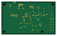
About the Mini biped robot PCB
Mini biped robot is an open source Microchip SAM PCB design by mrcha033, published on GitHub under the Apache-2.0 license. It is a 2-layer board measuring 50 × 30 mm, with 32 components from 29 distinct parts.
Its main chip is the ATSAMD21G18A-AU, from the Microchip SAM family. Other key parts include the AP2112K-3.3TRG1, LSM6DSOXTR, BME280, D24V90F5 and PCA9685PW. By type, the board carries 10 connectors, 7 ICs, 7 capacitors, 5 resistors, 1 crystal and 1 fuse.
It belongs with the robotics & motion and wearables designs in this gallery.
From the project
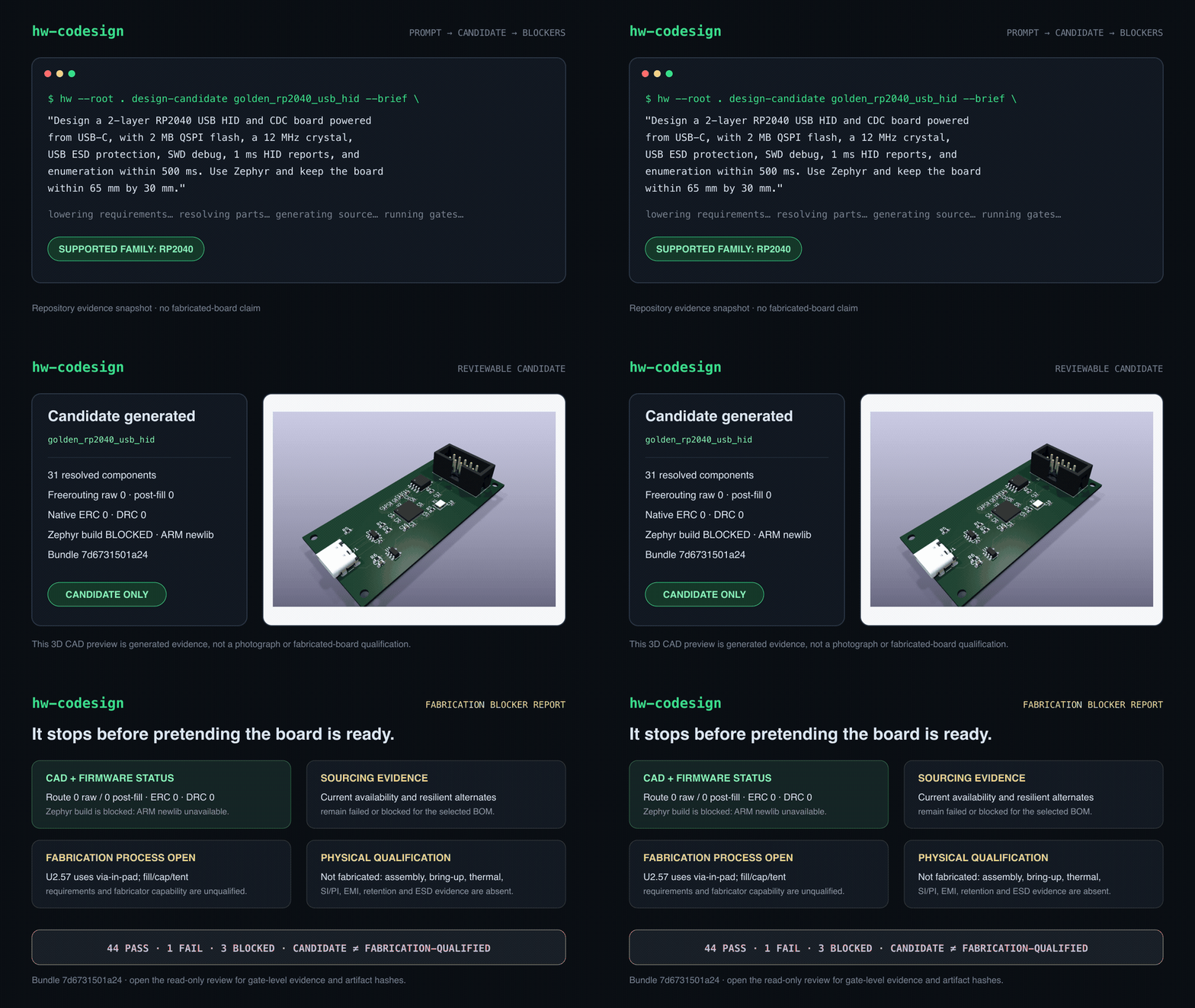
Agentic hardware co-design: brief to KiCad, firmware, 3D review, and explicit fabrication blockers.
Give an AI agent a hardware brief. Get KiCad, firmware, a 3D assembly, and an explicit fabrication-blocker report.
Agentic hardware co-design from brief to KiCad, firmware, 3D review, and explicit fabrication blockers. For 13 supported board families, hw-codesign turns a prompt into a reviewable candidate while keeping missing sourcing, toolchain, manufacturing, and physical evidence visible instead of silently treating it as success.
Main components on the Mini biped robot
Mini biped robot bill of materials (BOM)
32 components, 29 distinct parts — part numbers from the project's BOM.
| Qty | Part | Footprint | Refs |
|---|---|---|---|
| 1 | AP2112K-3.3TRG1 3V3 LDO | SOT-23-5 | U1 |
| 1 | ATSAMD21G18A-AU SAMD21G18A | TQFP-48_7x7mm_P0.5mm | U2 |
| 1 | LSM6DSOXTR LSM6DSOX | LGA-14_3x2.5mm_P0.5mm | U3 |
| 1 | BME280 | Bosch_LGA-8_2.5x2.5mm_P0.65mm | U4 |
| 1 | D24V90F5 5V 9A STEP-DOWN MODULE | MODULE_POLOLU_D24V90F5 | U20 |
| 1 | PCA9685PW 16-CHANNEL I2C PWM | TSSOP-28_4.4x9.7mm_P0.65mm | U21 |
| 1 | SN74LVC1G04DBVR E-STOP PWM INVERTER | SOT-23-5 | U22 |
| 1 | MC-306 32.768KHZ 32.768kHz XTAL | Crystal_SMD_Epson_MC-306_3.2x1.5mm | X1 |
| 1 | USB4105-GF-A USB-C POWER | USB_C_GCT_USB4105 | J1 |
| 1 | 61201021621 SWD 10-pin | PinHeader_2x05_P2.54mm_Vertical | J2 |
| 1 | XT30PW-M 2S LIPO INPUT | XT30PW_M | J20 |
| 1 | M20-9990345 SERVO_1_3PIN | PinHeader_1x03_P2.54mm_Vertical | J21 |
| 1 | M20-9990345 SERVO_2_3PIN | PinHeader_1x03_P2.54mm_Vertical | J22 |
| 1 | M20-9990345 SERVO_3_3PIN | PinHeader_1x03_P2.54mm_Vertical | J23 |
| 1 | M20-9990345 SERVO_4_3PIN | PinHeader_1x03_P2.54mm_Vertical | J24 |
| 1 | M20-9990345 SERVO_5_3PIN | PinHeader_1x03_P2.54mm_Vertical | J25 |
| 1 | M20-9990345 SERVO_6_3PIN | PinHeader_1x03_P2.54mm_Vertical | J26 |
| 1 | 1935161 NC E-STOP LOOP | TerminalBlock_1x03_P5.08mm | J27 |
| 1 | 0451010.MRL 10A SERVO FUSE | Fuseholder_Blade_Mini | F20 |
| 1 | USBLC6-2SC6 USB ESD | SOT-23-6 | D1 |
Show 9 more
| Qty | Part | Footprint | Refs |
|---|---|---|---|
| 2 | GRM155R71C104KA88D 100nF | C_0402_1005Metric | C1, C2 |
| 1 | GRM188R60J106ME47D 10uF | C_0603_1608Metric | C3 |
| 2 | GRM2165C1H120JA01D 12pF RTC XTAL | C_0805_2012Metric | C4, C5 |
| 1 | GRM188R61C105KA93D 1uF VDDCORE | C_0603_1608Metric | C6 |
| 1 | GRM188R60J106ME47D 1000uF 10V LOW ESR | C_0603_1608Metric | C20 |
| 1 | RC0603FR-074K7L 4K7 SCL PU | R_0603_1608Metric | R1 |
| 1 | RC0603FR-074K7L 4K7 SDA PU | R_0603_1608Metric | R2 |
| 2 | RC0603FR-075K1L 5K1 USB-C Rd | R_0603_1608Metric | R3, R4 |
| 1 | RC0603FR-0710KL 10K E-STOP FAIL-SAFE PULLDOWN | R0603 | R20 |
Mini biped robot design files
The KiCad project lives in the mrcha033/hw-codesign repository on GitHub; these links point at the commit this page was built from.
Mini biped robot: common questions
What microcontroller does the Mini biped robot use?
The Mini biped robot is built around the ATSAMD21G18A-AU, from the Microchip SAM family.
How big is the Mini biped robot PCB?
The Mini biped robot measures 50 × 30 mm, has 2 copper layers and is 1.6 mm thick.
How many components are on the Mini biped robot?
32 components, from 29 distinct parts, with part numbers taken from the project's own BOM. The full bill of materials is listed on this page.
Where can I download the Mini biped robot design files?
From the mrcha033/hw-codesign repository on GitHub, which has the KiCad layout, the schematic and the BOM; the links under Design files point to each one.
Can I use the Mini biped robot design in my own project?
Yes, under the terms of its Apache-2.0 license, which mrcha033 chose for the repository.
Can I test firmware for the Mini biped robot without the hardware?
Yes. HardLabs builds a simulation of the board from its netlist and BOM, so you can run and debug Microchip SAM firmware against it before you order a PCB.
More boards in hw-codesign
 STM32
STM32Bench robotics controller 5eab0a5d
160 × 100 mm42 parts4LApache-2.02 STM32
STM32Bench robotics controller b204035a
160 × 100 mm42 parts4LApache-2.02 STM32
STM32Quadruped robot controller
160 × 100 mm42 parts4LApache-2.02 RP2040/RP2350
Golden rp2040 usb hid
65 × 30 mm31 parts2LApache-2.02 Nordic nRF
Bench ble lipo sensor 5eab0a5d
50 × 35 mm19 parts2LApache-2.02 Nordic nRF
Bench ble lipo sensor b204035a
50 × 35 mm19 parts2LApache-2.02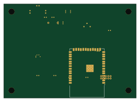 ESP32
ESP32Sensor data logger
70 × 50 mm16 parts2LApache-2.02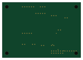 ESP32
ESP32Bench sensor logger usb b204035a
70 × 50 mm14 parts2LApache-2.02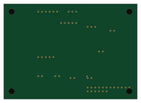 ESP32
ESP32Bench sensor logger usb 5eab0a5d
70 × 50 mm14 parts2LApache-2.02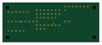 RP2040/RP2350
Bench rp2040 usb hid 5eab0a5d
51 × 21 mm11 parts2LApache-2.02 RP2040/RP2350
Bench rp2040 usb hid b204035a
51 × 21 mm11 parts2LApache-2.02
Similar boards
 Microchip SAM
Fpgaboy
Wren6991
50 × 50 mm89 parts4LNo license508 Microchip SAM
Kira
kiibohd
366.9 × 114.3 mm400 partsCERN-OHL-1.2415 Microchip SAM
DSKY driver
benkrasnow
43 × 92.3 mm44 partsMIT258 Microchip SAM
Duet 2 Maestro
Duet3D
100 × 123 mm336 partsCERN-OHL-1.2257 Microchip SAM
Mainboard
pycubed
90.2 × 95.9 mm196 parts2LNo license96 Microchip SAM
Tiny4FSK
New-England-Weather-Balloon-Society
35.1 × 76.3 mm80 parts4LCERN-OHL-W-2.095