
Esp32-iot-4layer

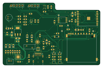
About the Esp32-iot-4layer PCB
Esp32-iot-4layer is an open source ESP32 PCB design by ODARI-CHARLES1, published on GitHub. It is a 4-layer board measuring 88.2 × 56.4 mm, with 79 components from 36 distinct parts.
Its main chip is the ESP32-C3-WROOM-02, from the ESP32 family. Other key parts include the MCP73871, USBLC6-2SC6, CP2102N-Axx-xQFN20, W25Q16JVSS and BME280. By type, the board carries 32 resistors, 21 capacitors, 7 ICs, 6 LEDs, 5 connectors and 3 transistors.
It belongs with the iot & wireless, power & battery and sensors designs in this gallery.
From the project
This project focuses on the design and development of a 4-layer PCB for an ESP32-based IoT device. The goal is to create a compact, robust, and EMI-optimized PCB layout suitable for IoT applications.
This project focuses on the design and development of a 4-layer PCB for an ESP32-based IoT device. The goal is to create a compact, robust, and EMI-optimized PCB layout suitable for IoT applications.
- Microcontroller: ESP32-WROOM-32 (or compatible module) - PCB Layers: 4 (Signal–Ground–Power–Signal stackup) - Purpose: General-purpose IoT hardware platform for prototyping and deployment - Tools Used: KiCad (v6/v7), Git for version control
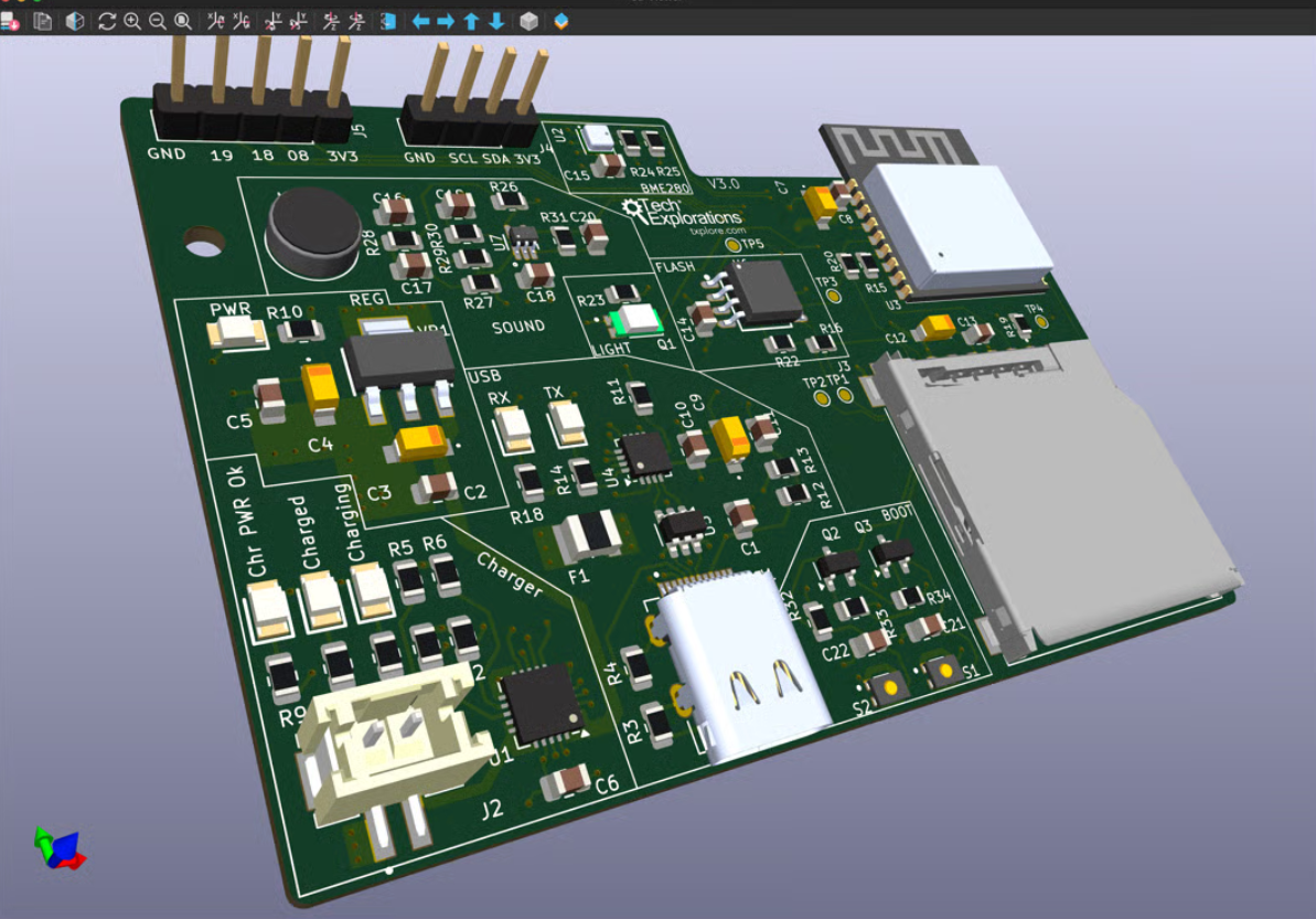
Main components on the Esp32-iot-4layer
Esp32-iot-4layer bill of materials (BOM)
79 components, 36 distinct parts.
| Qty | Part | Footprint | Refs |
|---|---|---|---|
| 1 | MCP73871 | QFN-20-1EP_4x4mm_P0.5mm_EP2.5x2.5mm | U1 |
| 1 | USBLC6-2SC6 | SOT-23-6 | U2 |
| 1 | ESP32-C3-WROOM-02 | ESP32-C3-WROOM-02 | U3 |
| 1 | CP2102N-Axx-xQFN20 | WFQFN-20 | U4 |
| 1 | W25Q16JVSS | SOIC-8_5.3x5.3mm_P1.27mm | U5 |
| 1 | BME280 | Bosch_LGA-8_2.5x2.5mm_P0.65mm_ClockwisePinNumbering | U6 |
| 1 | MAX4466EXK | SOT65P210X110-5N | U7 |
| 1 | TEMT6000X01 | TRANS_TEMT6000X01 | Q1 |
| 2 | BC817 | SOT-23 | Q2, Q3 |
| 1 | SS-52400-003 Stewart Connector | BELFUSE_SS-52400-003 | J1 |
| 1 | B2B-PH-K-S_LF__SN_ | JST_B2B-PH-K-S_LF__SN_ | J2 |
| 1 | GSD090012SEU | AMPHENOL_GSD090012SEU | J3 |
| 1 | Conn_01x04_Pin | PinHeader_1x04_P2.54mm_Vertical | J4 |
| 1 | Conn_01x05_Pin | PinHeader_1x05_P2.54mm_Vertical | J5 |
| 1 | Polyfuse_Small | Fuse_BelFuse_0ZRE0016FF_L9.9mm_W3.8mm | F1 |
| 1 | CMC-5042PF-AC | CUI_CMC-5042PF-AC | MK1 |
| 2 | USLPT2819DT2TR | SW_USLPT2819DT2TR | S1, S2 |
| 1 | LM1117MPX-3.3/NOPB LM1117MPX-3.3_NOPB Texas Instruments | VREG_LM1117MPX-3.3_NOPB | VR1 |
| 4 | LTST-C170KGKT | LED_0805_2012Metric | LED1, LED2, LED5, LED6 |
| 2 | LTST-C170KRKT | LED_0805_2012Metric | LED3, LED4 |
Show 16 more
| Qty | Part | Footprint | Refs |
|---|---|---|---|
| 13 | 0.1u | C_0805_2012Metric | C1, C2, C5, C6, C8, C10, C13, C14 +5 |
| 4 | 10u | CAPMP3216X180N | C3, C4, C7, C12 |
| 1 | 4.7u | CAPMP3216X180N | C9 |
| 2 | 1u | C_0805_2012Metric | C11, C22 |
| 1 | 10n | C_0805_2012Metric | C17 |
| 6 | 470R | R_0805_2012Metric | R1, R2, R9, R10, R14, R18 |
| 2 | 5K1 | R_0805_2012Metric | R3, R4 |
| 10 | 10K | R_0805_2012Metric | R5, R6, R7, R8, R19, R23, R30, R32 +2 |
| 1 | 1k | R_0805_2012Metric | R11 |
| 1 | 22.1K | R_0805_2012Metric | R12 |
| 1 | 47K5 | R_0805_2012Metric | R13 |
| 4 | 50 | R_0805_2012Metric | R15, R16, R20, R22 |
| 2 | 4K7 | R_0805_2012Metric | R24, R25 |
| 2 | 2K | R_0805_2012Metric | R26, R28 |
| 2 | 1M | R_0805_2012Metric | R27, R29 |
| 1 | 100K | R_0805_2012Metric | R31 |
Esp32-iot-4layer design files
The KiCad project lives in the ODARI-CHARLES1/esp32-iot-4layer-pcb repository on GitHub; these links point at the commit this page was built from.
- LayoutPROJECT_PCB.kicad_pcb
- SchematicPROJECT_PCB.kicad_sch
Esp32-iot-4layer: common questions
What microcontroller does the Esp32-iot-4layer use?
The Esp32-iot-4layer is built around the ESP32-C3-WROOM-02, from the ESP32 family.
How big is the Esp32-iot-4layer PCB?
The Esp32-iot-4layer measures 88.2 × 56.4 mm, has 4 copper layers and is 1.6 mm thick.
How many components are on the Esp32-iot-4layer?
79 components, from 36 distinct parts. The full bill of materials is listed on this page.
Where can I download the Esp32-iot-4layer design files?
From the ODARI-CHARLES1/esp32-iot-4layer-pcb repository on GitHub, which has the KiCad layout and the schematic; the links under Design files point to each one.
Can I use the Esp32-iot-4layer design in my own project?
The repository has no license, so all rights stay with ODARI-CHARLES1. Use it as a reference, and ask the author before reusing the design.
Can I test firmware for the Esp32-iot-4layer without the hardware?
Yes. HardLabs builds a simulation of the board from its netlist and BOM, so you can run and debug ESP32 firmware against it before you order a PCB.
Similar boards
 ESP32
ESP32Open Book Abridged Edition
joeycastillo
85 × 115 mm65 parts2LCC-BY-SA-4.08.1k ESP32
ESP32Badge
atopile
56.3 × 39 mm239 parts4LMIT4.0k ESP32
ESP32Esp32 minimal
36.2 × 26.8 mm20 parts2LMIT4.0k ESP32
ESP32Racer
StuckAtPrototype
36 × 50.2 mm70 parts4LApache-2.03.8k ESP32
ESP32Controller
29 × 74 mm58 parts4LApache-2.03.8k ESP32
ESP32Bitaxe
skot
56.5 × 99.8 mm86 parts4LCERN-OHL-S-2.01.4k