
ControlBoard

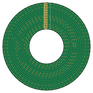
About the ControlBoard PCB
ControlBoard is an open source ESP32 PCB design by paradise-fi, published on GitHub under the CC-BY-NC-4.0 license. It is a 4-layer board measuring 76 × 76 mm, with 207 components from 89 distinct parts.
Its main chip is the ESP32-WROVER-E-N16R8, from the ESP32 family. Other key parts include the Servo, SD8942, TPS61088, MPU-6050 and PIEZO. By type, the board carries 60 capacitors, 44 connectors, 40 resistors, 12 ICs, 8 diodes and 5 switches.
It belongs with the robotics & motion designs in this gallery.
From the project
Distributed Metamorphic Robots
- universalModule.f3z - CAD drawing of module (Fusion 360) - RoFILEGO.f3z - CAD drawing of a small model (Fusion 360) - see its page for more details - controlBoard - PCB for the electronics powering the module - slipRing & slipRingBrush - custom slip ring for the module
The provided makefile exports all Gerber files for PCB manufacturing as zip files.
Main components on the ControlBoard
ControlBoard bill of materials (BOM)
207 components, 89 distinct parts.
| Qty | Part | Footprint | Refs |
|---|---|---|---|
| 3 | Servo | Dynamixel-XL-430-TOP | U1, U2, U3 |
| 1 | SD8942 | SOT-23-6 | U4 |
| 2 | TPS61088 | VFQFN-20-4.5mmx3.5mm | U5, U8 |
| 1 | ESP32-WROVER-E-N16R8 | ESP32-WROVER | U6 |
| 1 | MPU-6050 | InvenSense_QFN-24_4x4mm_P0.5mm | U7 |
| 1 | PIEZO CST-931AP | CST-931AP | U9 |
| 1 | TP5100 | QFN-16-1EP_4x4mm_P0.65mm_EP2.1x2.1mm | U10 |
| 1 | STM32F411CEUx | QFN-48-1EP_7x7mm_P0.5mm_EP5.6x5.6mm | U11 |
| 1 | HT7533-1-SOT89 | SOT-89-3 | U12 |
| 2 | AONR21357 | DFN3.3X3.3-EP | Q1, Q2 |
| 1 | 2N7002 | SOT-23 | Q3 |
| 1 | 7D024000H01 | Crystal_SMD_2016-4Pin_2.0x1.6mm | Y1 |
| 2 | DEBUG FH12-10S-0.5SH(55) | Hirose_FH12-10S-0.5SH_1x10-1MP_P0.50mm_Horizontal | J1, J21 |
| 1 | OLED_DISPLAY | OLED_128_32_I2C | J2 |
| 1 | BOARD_IN FH12-40S-0.5SH(55) | Hirose_FH12-40S-0.5SH_1x40-1MP_P0.50mm_Horizontal | J3 |
| 1 | SERVO | PinHeader_1x03_P2.54mm_Vertical | J4 |
| 1 | SHOE_B1 120220-0161 | SlipRing-120220-0161 | J5 |
| 1 | SHOE_B2 120220-0204 | SlipRing-120220-0161-incomplete | J6 |
| 1 | BATTERY_BOARD_CONN TMM-112-06-T-D-SM | PinHeader_2x12_P2.00mm_Vertical | J7 |
| 1 | USB_C_Receptacle_USB2.0 | USB_C_Female-16Pin-HPJF | J8 |
Show 69 more
| Qty | Part | Footprint | Refs |
|---|---|---|---|
| 1 | INTERFACE_CONN_BOTTOM M22-6550642R | PinHeader_2x12_P2.00mm_Vertical | J9 |
| 1 | INTERFACE_CONN_TOP M22-6550642R | 2xM22-6550642R | J10 |
| 1 | CONTROL_BOARD_CONN TMM-112-06-T-D-SM | PinHeader_2x12_P2.00mm_Vertical_SMD | J11 |
| 1 | SHOE FH12-24S-0.5SH(55) | Hirose_FH12-24S-0.5SH_1x24-1MP_P0.50mm_Horizontal | J12 |
| 2 | SLIP_RING_OUT FH12-40S-0.5SH(55) | Hirose_FH12-40S-0.5SH_1x40-1MP_P0.50mm_Horizontal | J13, J48 |
| 1 | REFERENCE_PINS | SlipRing-120220-0161 | J14 |
| 1 | INPUT | FPC_0.5_24_PADS | J15 |
| 1 | ST-LINK A 75869-101LF | IDC-Header_2x05_P2.54mm_Vertical | J16 |
| 1 | ST-LINK_B 75869-101LF | IDC-Header_2x05_P2.54mm_Vertical | J17 |
| 1 | Conn_02x10_Odd_Even | PinSocket_2x10_P2.54mm_Vertical | J18 |
| 1 | ESP-DBG 75869-101LF | IDC-Header_2x05_P2.54mm_Vertical | J19 |
| 1 | Conn_ST_STDC14 FTSH-107-01-L-DV-K-A | PinSocket_2x07_P1.27mm_Vertical_SMD | J20 |
| 1 | SHOE_OUT FH12-40S-0.5SH(55) | Hirose_FH12-40S-0.5SH_1x40-1MP_P0.50mm_Horizontal | J22 |
| 3 | ROFICOM1_A 009258008004064 | SOLO-9258 | J23, J29, J35 |
| 3 | DBG1 | PinHeader_1x07_P2.54mm_Vertical | J24, J30, J36 |
| 3 | ROFICOM1_B 009258008004064 | SOLO-9258 | J25, J31, J37 |
| 3 | ROFICOM1_C 009258008004064 | SOLO-9258 | J26, J32, J38 |
| 3 | OUTPUT | UM_SHOE_PADS | J27, J33, J39 |
| 2 | INPUT | UM_SHOE_PADS | J28, J34 |
| 1 | A | UM_SHOE_PADS_BOTH | J40 |
| 1 | B | UM_SHOE_PADS_BOTH | J41 |
| 2 | SHOE | FPC_0.5_24_PADS | J42, J44 |
| 11 | BOARD | Board | BODY1, BODY2, BODY3, BODY4, BODY5, CABLE1, CABLE2, DEBUG1 +3 |
| 2 | Battery_Cell | BATTERY_18350 | BT1, BT2 |
| 16 | MountingHole | ThreadedHole-M2 | H16, H17, H18, H19, H20, H21, H22, H23 +8 |
| 1 | BootSelector | SolderJumper-3_P2.0mm_Open_TrianglePad1.0x1.5mm | JP1 |
| 1 | SW_LEFT | BUTTON_SMT_G_4_3 | SW1 |
| 1 | STOP_BUTTON | BUTTON_SMT_G_4_3 | SW2 |
| 1 | SW_MID | BUTTON_SMT_G_4_3 | SW3 |
| 1 | START_BUTTON | BUTTON_SMT_G_4_3 | SW4 |
| 1 | SW_RIGHT | BUTTON_SMT_G_4_3 | SW5 |
| 1 | SM4007PL | D_SOD-123F | D1 |
| 2 | SB1045L | TO-277B | D2, D3 |
| 1 | SS54 | D_SMA | D4 |
| 1 | RED | LED_0603_1608Metric | D14 |
| 3 | GREEN | LED_0603_1608Metric | D16, D17, D18 |
| 2 | 1u5/2u2 MGV10043R3M-10 | MGV1004 | L1, L2 |
| 1 | 4u7 | SMNR5020 | L3 |
| 1 | 22u | SLO0630H | L4 |
| 27 | 22u | C_0805_2012Metric | C1, C4, C5, C6, C7, C8, C10, C12 +19 |
| 2 | 2u2 | C_0603_1608Metric | C9, C11 |
| 4 | 100n | C_0603_1608Metric | C14, C15, C16, C17 |
| 3 | 1u | C_0603_1608Metric | C18, C23, C24 |
| 2 | 22n | C_0402_1005Metric | C21, C22 |
| 2 | 27p | C_0402_1005Metric | C31, C33 |
| 2 | 470p | C_0402_1005Metric | C36, C44 |
| 8 | 470n | C_0402_1005Metric | C41, C42, C43, C51, C59, C62, C63, C64 |
| 6 | 100n | C_0402_1005Metric | C45, C46, C47, C53, C54, C57 |
| 2 | 10p | C_0402_1005Metric | C52, C65 |
| 1 | 10u | C_0805_2012Metric | C55 |
| 1 | 10u | C_0402_1005Metric | C60 |
| 1 | 200k | R_0402_1005Metric | R1 |
| 9 | 10k | R_0402_1005Metric | R2, R17, R22, R27, R30, R32, R34, R36 +1 |
| 2 | 150k | C_0402_1005Metric | R3, R4 |
| 3 | 0R | R_0402_1005Metric | R5, R6, R19 |
| 4 | 100k | R_0402_1005Metric | R7, R24, R25, R26 |
| 1 | 22k | R_0402_1005Metric | R8 |
| 2 | 75k | R_0402_1005Metric | R9, R10 |
| 2 | 47k | R_0402_1005Metric | R11, R12 |
| 2 | 510k | R_0402_1005Metric | R13, R15 |
| 2 | 56k | R_0402_1005Metric | R14, R16 |
| 1 | 470R | R_0402_1005Metric | R18 |
| 1 | 75m | R_1206_3216Metric | R20 |
| 2 | 68k | R_0402_1005Metric | R21, R23 |
| 2 | 3k3 | R_0402_1005Metric | R28, R29 |
| 1 | 20k | R_0402_1005Metric | R31 |
| 2 | 2k2 | R_0402_1005Metric | R33, R35 |
| 2 | 5k1 | R_0402_1005Metric | R37, R38 |
| 1 | 1k | R_0402_1005Metric | R55 |
ControlBoard design files
The KiCad project lives in the paradise-fi/RoFI repository on GitHub; these links point at the commit this page was built from.
ControlBoard: common questions
What microcontroller does the ControlBoard use?
The ControlBoard is built around the ESP32-WROVER-E-N16R8, from the ESP32 family.
How big is the ControlBoard PCB?
The ControlBoard measures 76 × 76 mm, has 4 copper layers and is 1.6 mm thick.
How many components are on the ControlBoard?
207 components, from 89 distinct parts. The full bill of materials is listed on this page.
Where can I download the ControlBoard design files?
From the paradise-fi/RoFI repository on GitHub, which has the KiCad layout and the schematic; the links under Design files point to each one.
Can I use the ControlBoard design in my own project?
It is published under CC-BY-NC-4.0, which limits how it may be reused; read the license before building on it.
Can I test firmware for the ControlBoard without the hardware?
Yes. HardLabs builds a simulation of the board from its netlist and BOM, so you can run and debug ESP32 firmware against it before you order a PCB.
More boards in RoFI
Similar boards
 ESP32
ESP32Open Book Abridged Edition
joeycastillo
85 × 115 mm65 parts2LCC-BY-SA-4.08.1k ESP32
ESP32Badge
atopile
56.3 × 39 mm239 parts4LMIT4.0k ESP32
ESP32Esp32 minimal
36.2 × 26.8 mm20 parts2LMIT4.0k ESP32
ESP32Racer
StuckAtPrototype
36 × 50.2 mm70 parts4LApache-2.03.8k ESP32
ESP32Controller
29 × 74 mm58 parts4LApache-2.03.8k ESP32
ESP32Bitaxe
skot
56.5 × 99.8 mm86 parts4LCERN-OHL-S-2.01.4k