
IO-SDR

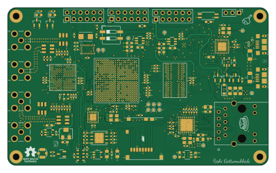
About the IO-SDR PCB
IO-SDR is an open source FPGA PCB design by rishivg, published on GitHub under the CERN-OHL-S-2.0 license. It is a 8-layer board measuring 99.4 × 60 mm, with 309 components from 99 distinct parts.
Its main chip is the XC7Z010-1CLG400I, from the FPGA family. Other key parts include the TCMT1107, SY6280AAC, TCS4615, TPS7A8101DRBT and RT9193-33B. By type, the board carries 146 capacitors, 52 resistors, 20 ICs, 14 inductors, 13 connectors and 4 transistors.
It belongs with the rf & radio designs in this gallery.
From the project
Open-Source software-defined FPGA radio hardware platform
IO-SDR is an open-source software-defined FPGA radio hardware platform that serves as a successor to the Pluto SDR Learning Module. Support includes and is not limited to:
- dual multichannel transmission and reception - Gigabit Ethernet connection - Embedded Linux SoC development - GNU Radio blocks
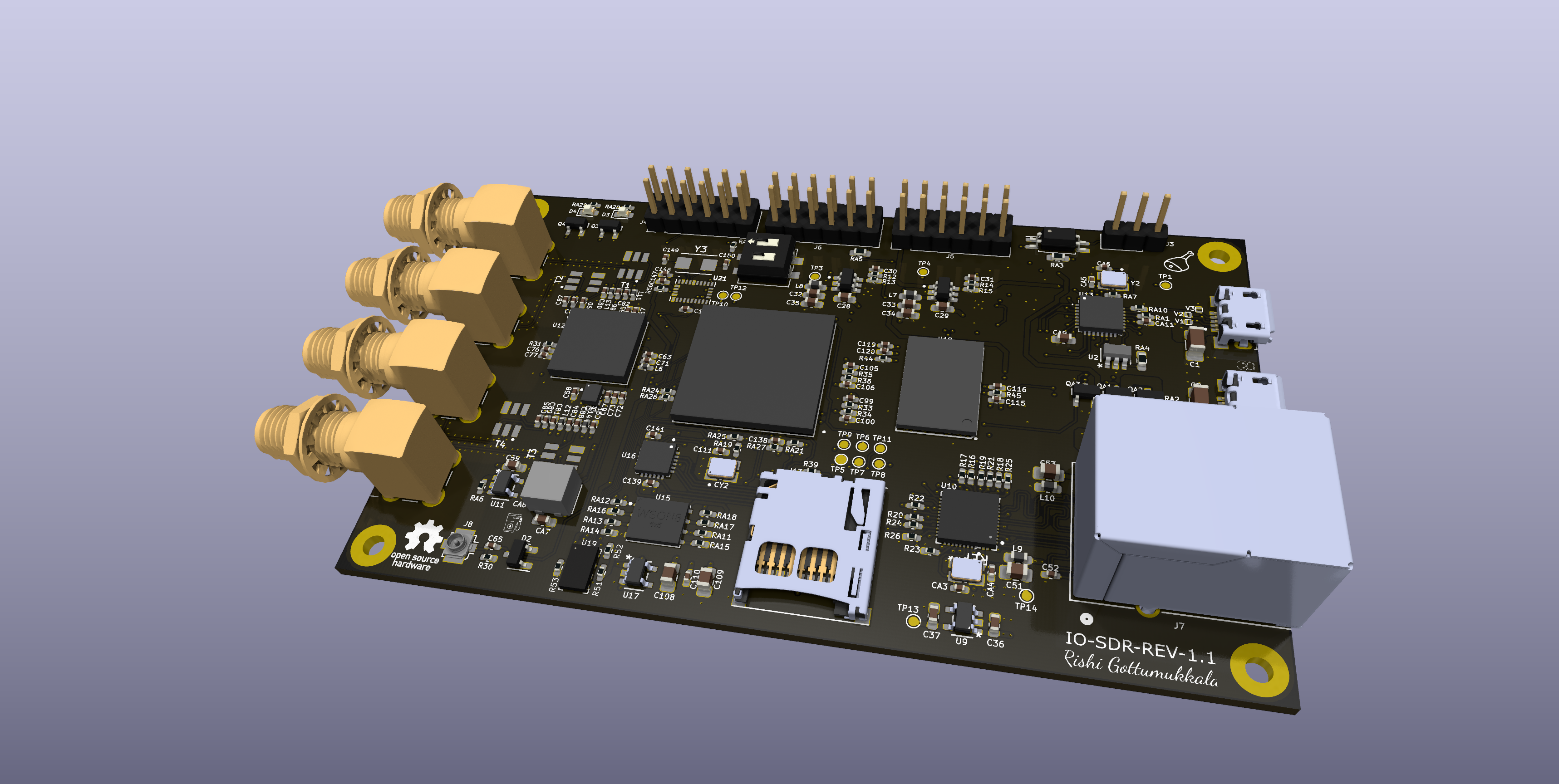
Main components on the IO-SDR
IO-SDR bill of materials (BOM)
309 components, 99 distinct parts — part numbers from the project's BOM.
| Qty | Part | Footprint | Refs |
|---|---|---|---|
| 1 | TCMT1107 | SOP-4_4.4x2.6mm_P1.27mm | U1 |
| 1 | SY6280AAC | SY6280AAC | U2 |
| 4 | TCS4615 | TCS4615 | U3, U4, U7, U8 |
| 2 | TPS7A8101DRBT | TPS7A8101DRBT | U5, U6 |
| 3 | RT9193-33B | RT9193-33B | U9, U11, U17 |
| 1 | RTL8211E-VB-CG | RTL8211E-VB-CG | U10 |
| 1 | AD9361BBCZ | AD9361BBCZ | U12 |
| 1 | USB3320C-EZK USB3320C-EZK-TR | USB3320C-EZK-TR | U13 |
| 1 | XC7Z010-1CLG400I | XC7Z010-1CLG400I | U14 |
| 1 | MX25U1635EZNI-10G | MX25U1635EZNI-10G | U15 |
| 1 | TXS02612RTWR | TXS02612RTWR | U16 |
| 1 | H5TQ4G63AFR | H5TQ4G63AFR | U18 |
| 1 | MS5611-01BA | LGA-8_3x5mm_P1.25mm | U19 |
| 1 | BNO085 | IC_BNO080 | U21 |
| 2 | S8050 | SOT-23 | Q1, Q2 |
| 2 | ~ | SOT23 MOSFET FOOT PRINT | Q3, Q4 |
| 1 | TSX-3225_25.0000MF10P-C0 25MHz | XTAL_TSX-3225_25.0000MF10P-C0 | Y1 |
| 1 | 25MHZ 25MHz | XTAL_TSX-3225_25.0000MF10P-C0 | Y2 |
| 1 | 32.768KHZ 32.768kHz | Crystal_SMD_Qantek_QC5CB-2Pin_5x3.2mm | Y3 |
| 2 | 10118193-0001LF | AMPHENOL_10118193-0001LF | J1, J2 |
Show 79 more
| Qty | Part | Footprint | Refs |
|---|---|---|---|
| 1 | CONN_01X03_SHIELDED Conn_01x03_Shielded | PinHeader_1x03_P2.54mm_Vertical | J3 |
| 3 | CON12-254 | PinHeader_2x06_P2.54mm_Vertical | J4, J5, J6 |
| 1 | HR911130A1 | HR911130A_HAN | J7 |
| 1 | 73412-0110 | U.FL_Molex_MCRF_73412-0110_Vertical | J8 |
| 4 | RF2-49B-T-00-50-G-HDW | ADAMTECH_RF2-49B-T-00-50-G-HDW | J9, J10, J11, J12 |
| 1 | 502570-0893 | MOLEX_502570-0893 | J13 |
| 3 | 0.1UF 0.1uF | C_0402_1005Metric_Pad0.74x0.62mm_HandSolder | CA1, CA8, CA11 |
| 3 | 10UF 10uF | C_0603_1608Metric_Pad1.08x0.95mm_HandSolder | CA2, CA7, CA9 |
| 2 | 12PF 12pF | C_0402_1005Metric_Pad0.74x0.62mm_HandSolder | CA3, CA4 |
| 2 | 18PF 18pF | C_0402_1005Metric_Pad0.74x0.62mm_HandSolder | CA5, CA6 |
| 1 | 4.7UF 4.7uF | C_0603_1608Metric_Pad1.08x0.95mm_HandSolder | CA10 |
| 1 | ASDMB-33.333MHZ-LC-T | XTAL_ASDMB-33.333MHZ-LC-T | CY1 |
| 1 | 33.333MHZ 33.333MHz | XTAL_ABM8AIG-25.000MHZ-12-2Z-T3 | CY2 |
| 3 | HR8031GS6 | HR8031GS6 | QA1, QA2, QA3 |
| 2 | 2.4K | R_0402_1005Metric_Pad0.72x0.64mm_HandSolder | RA1, RA2 |
| 1 | 4.7K | R_0603_1608Metric_Pad0.98x0.95mm_HandSolder | RA3 |
| 1 | 5.1K | R_0603_1608Metric_Pad0.98x0.95mm_HandSolder | RA4 |
| 1 | 0R | R_0603_1608Metric_Pad0.98x0.95mm_HandSolder | RA5 |
| 1 | 10K | R_0402_1005Metric_Pad0.72x0.64mm_HandSolder | RA6 |
| 1 | 1M | R_0402_1005Metric_Pad0.72x0.64mm_HandSolder | RA7 |
| 1 | 14.3K | R_0402_1005Metric_Pad0.72x0.64mm_HandSolder | RA8 |
| 11 | 20K | R_0402_1005Metric_Pad0.72x0.64mm_HandSolder | RA9, RA11, RA13, RA15, RA16, RA17, RA21, RA22 +3 |
| 1 | 8.06K | R_0402_1005Metric_Pad0.72x0.64mm_HandSolder | RA10 |
| 3 | 1K | R_0402_1005Metric_Pad0.72x0.64mm_HandSolder | RA12, RA14, RA18 |
| 2 | 33R | R_0402_1005Metric_Pad0.72x0.64mm_HandSolder | RA19, RA20 |
| 2 | 100K | R_0402_1005Metric_Pad0.72x0.64mm_HandSolder | RA24, RA26 |
| 2 | 4.7K | R_0402_1005Metric_Pad0.72x0.64mm_HandSolder | RA28, RA29 |
| 1 | SW_DIP_X02 SW_DIP_x02 | SW_DIP_SPSTx02_Slide_6.7x6.64mm_W6.73mm_P2.54mm_LowProfile_JPin | SW1 |
| 4 | TCM1-63AX_ | XFMR_TCM1-63AX_ | T1, T2, T3, T4 |
| 3 | HR02X5V | HR02X5V | V1, V2, V3 |
| 1 | SUPK24 | D_SOD-123 | D1 |
| 1 | SUP5522F | SOT-23-3 | D2 |
| 2 | LED6 | LED_0603_1608Metric_Pad1.05x0.95mm_HandSolder | D3, D4 |
| 5 | 2.2UH 2.2uH | L_0603_1608Metric_Pad1.05x0.95mm_HandSolder | L1, L4, L7, L8, L9 |
| 1 | R0603 | L_0603_1608Metric_Pad1.05x0.95mm_HandSolder | L2 |
| 2 | R0805 | L_0805_2012Metric_Pad1.05x1.20mm_HandSolder | L3, L5 |
| 1 | R0402 | L_0402_1005Metric_Pad0.77x0.64mm_HandSolder | L6 |
| 1 | BLM18PG181SN1 | L_0603_1608Metric_Pad1.05x0.95mm_HandSolder | L10 |
| 2 | 330NH 330nH | L_0402_1005Metric_Pad0.77x0.64mm_HandSolder | L11, L13 |
| 2 | 330NF 330nF | L_0402_1005Metric_Pad0.77x0.64mm_HandSolder | L12, L14 |
| 2 | 22UF 22uF | C_1206_3216Metric_Pad1.33x1.80mm_HandSolder | C1, C2 |
| 1 | 100UF 100uF | C_0805_2012Metric_Pad1.18x1.45mm_HandSolder | C3 |
| 1 | 22UF 22uF | C_0805_2012Metric_Pad1.18x1.45mm_HandSolder | C4 |
| 4 | 10UF 10uF | C_0805_2012Metric_Pad1.18x1.45mm_HandSolder | C5, C51, C108, C109 |
| 16 | 10UF 10uF | C_0603_1608Metric_Pad1.08x0.95mm_HandSolder | C6, C11, C12, C13, C15, C16, C18, C19 +8 |
| 2 | 10UF 10uF | C_1206_3216Metric_Pad1.33x1.80mm_HandSolder | C7, C8 |
| 1 | 1UF 1uF | C_0805_2012Metric_Pad1.18x1.45mm_HandSolder | C9 |
| 6 | 100PF 100pF | C_0402_1005Metric_Pad0.74x0.62mm_HandSolder | C10, C14, C30, C31, C119, C120 |
| 23 | 0.1UF 0.1uF | C_0402_1005Metric_Pad0.74x0.62mm_HandSolder | C17, C20, C38, C40, C41, C42, C43, C44 +15 |
| 4 | 47UF 47uF | C_1206_3216Metric_Pad1.33x1.80mm_HandSolder | C21, C23, C26, C27 |
| 30 | 10NF 10nF | C_0402_1005Metric_Pad0.74x0.62mm_HandSolder | C22, C24, C52, C54, C55, C60, C61, C64 +22 |
| 1 | 10UF 10uF | C_0603_1608Metric | C36 |
| 2 | 4.7UF 4.7uF | C_0603_1608Metric_Pad1.08x0.95mm_HandSolder | C37, C50 |
| 17 | 100NF 100nF | C_0402_1005Metric_Pad0.74x0.62mm_HandSolder | C39, C80, C81, C90, C91, C99, C100, C105 +9 |
| 1 | 0.1UF 0.1uF | C_0805_2012Metric_Pad1.18x1.45mm_HandSolder | C53 |
| 12 | 1UF 1uF | C_0402_1005Metric_Pad0.74x0.62mm_HandSolder | C56, C57, C58, C62, C63, C68, C70, C111 +4 |
| 12 | 18PF 18pF | C_0402_1005Metric_Pad0.74x0.62mm_HandSolder | C65, C67, C72, C73, C82, C83, C84, C85 +4 |
| 4 | 1NF 1nF | C_0402_1005Metric_Pad0.74x0.62mm_HandSolder | C76, C77, C78, C79 |
| 5 | 10UF 10uF | C_0402_1005Metric_Pad0.74x0.62mm_HandSolder | C94, C95, C96, C113, C135 |
| 2 | 22PF 22pf | C_0402_1005Metric_Pad0.74x0.62mm_HandSolder | C149, C150 |
| 1 | 33R | R_0402_1005Metric_Pad0.72x0.64mm_HandSolder | R1 |
| 6 | 10K | R_0402_1005Metric_Pad0.72x0.64mm_HandSolder | R2, R3, R7, R15, R22, R56 |
| 3 | 7.5K | R_0402_1005Metric_Pad0.72x0.64mm_HandSolder | R4, R8, R10 |
| 1 | 2K | R_0402_1005Metric_Pad0.72x0.64mm_HandSolder | R5 |
| 1 | 20K | R_0402_1005Metric_Pad0.72x0.64mm_HandSolder | R6 |
| 2 | 12K | R_0402_1005Metric_Pad0.72x0.64mm_HandSolder | R9, R11 |
| 1 | 3.3K | R_0402_1005Metric_Pad0.72x0.64mm_HandSolder | R12 |
| 10 | 4.7K | R_0402_1005Metric_Pad0.72x0.64mm_HandSolder | R13, R39, R40, R41, R42, R43, R46, R51 +2 |
| 1 | 15K | R_0402_1005Metric_Pad0.72x0.64mm_HandSolder | R14 |
| 8 | 4K7 | R_0402_1005Metric_Pad0.72x0.64mm_HandSolder | R16, R17, R18, R19, R20, R24, R25, R26 |
| 1 | 1K5 | R_0402_1005Metric_Pad0.72x0.64mm_HandSolder | R21 |
| 1 | 2.49K%1 | R_0402_1005Metric_Pad0.72x0.64mm_HandSolder | R23 |
| 2 | 510R R0402 5% | R_0402_1005Metric_Pad0.72x0.64mm_HandSolder | R27, R28 |
| 1 | 50K | Potentiometer_Bourns_3214W_Vertical | R29 |
| 1 | ESD | R_0402_1005Metric_Pad0.72x0.64mm_HandSolder | R30 |
| 2 | 1R | R_0402_1005Metric_Pad0.72x0.64mm_HandSolder | R31, R32 |
| 6 | 2.4K | R_0402_1005Metric_Pad0.72x0.64mm_HandSolder | R33, R34, R35, R36, R44, R45 |
| 3 | 80.5R | R_0402_1005Metric_Pad0.72x0.64mm_HandSolder | R37, R38, R48 |
| 1 | 240R | R_0402_1005Metric_Pad0.72x0.64mm_HandSolder | R47 |
IO-SDR design files
The KiCad project lives in the rishivg/IO-SDR repository on GitHub; these links point at the commit this page was built from.
IO-SDR: common questions
What microcontroller does the IO-SDR use?
The IO-SDR is built around the XC7Z010-1CLG400I, from the FPGA family.
How big is the IO-SDR PCB?
The IO-SDR measures 99.4 × 60 mm, has 8 copper layers and is 1.620266 mm thick.
How many components are on the IO-SDR?
309 components, from 99 distinct parts, with part numbers taken from the project's own BOM. The full bill of materials is listed on this page.
Where can I download the IO-SDR design files?
From the rishivg/IO-SDR repository on GitHub, which has the KiCad layout, the schematic and the BOM; the links under Design files point to each one.
Can I use the IO-SDR design in my own project?
Yes, under the terms of its CERN-OHL-S-2.0 license, which rishivg chose for the repository.
Can I test firmware for the IO-SDR without the hardware?
Yes. HardLabs builds a simulation of the board from its netlist and BOM, so you can run and debug FPGA firmware against it before you order a PCB.
Similar boards
 FPGA
FPGABase board
GlasgowEmbedded
80 × 49 mm222 parts4L0BSD2.2k FPGA
FPGAThunderscope Rev5.3
EEVengers
122.5 × 103.5 mm817 parts6LMIT1.3k FPGA
FPGAIcepi zero
cheyao
65 × 30 mm143 parts4LSHL-2.1828 FPGA
FPGARadioberry
pa3gsb
65 × 56 mm143 parts4LNo license675 FPGA
FPGAHaasoscopePro
drandyhaas
224.5 × 160 mm586 parts10LMIT471 FPGA
FPGAFomu hardware
im-tomu
90 × 50 mm57 parts2LCC-BY-SA-4.0235