
RetroCom Station2

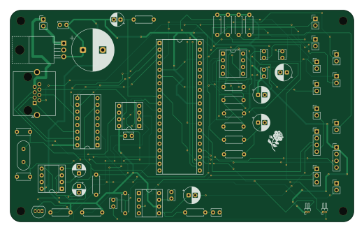
About the RetroCom Station2 PCB
RetroCom Station2 is an open source PCB design by SamyIOoOI, published on GitHub under the GPL-3.0 license. It is a 2-layer board measuring 130 × 80 mm, with 59 components from 41 distinct parts.
Other key parts include the MAX485E, TL072, LM386, uA7805 and ICL7660. By type, the board carries 18 capacitors, 16 resistors, 8 ICs, 5 switches, 4 diodes and 1 transistor.
It belongs with the retro computing designs in this gallery.
From the project
A 4-Station one-to-one two-way INTERCOM built around the AT89C52-PI24 RetroMCU (8051 Core).
- AT89C52-PI24 MCU per Station. [Handles Interstation Communication & Interface]. - Supports two-way simultaneous speech. No taking turns when talking. RetroCom functions just like a phonecall. - All stations are connected to main station directly via CAT6 Cables. Distances of 20M (Meters) to 30M are OK . - Switching is done by CD4051 & CD4052 ICs powered with negative & postive 5 V Rails. PreAmped Signals face no distortion. - Audio undergoes a preamp stage under the TL072 & power amp stage under the LM386. - The main station has a built in Radio Module. [As of Version 1.0 [WIRED] the radio…
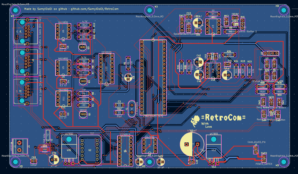
Main components on the RetroCom Station2
RetroCom Station2 bill of materials (BOM)
59 components, 41 distinct parts — part numbers from the project's BOM.
| Qty | Part | Footprint | Refs |
|---|---|---|---|
| 1 | MAX485E | DIP-8_W7.62mm_Socket | U1 |
| 1 | TL072 | DIP-8_W7.62mm_Socket | U2 |
| 1 | LM386 | DIP-8_W7.62mm_Socket | U3 |
| 1 | uA7805 | TO-220-3_Horizontal_TabUp | U5 |
| 1 | ICL7660 | DIP-8_W7.62mm_Socket | U6 |
| 1 | AT89C55WD-24PU | DIP-40_W15.24mm_Socket | U7 |
| 1 | CD4051B | DIP-16_W7.62mm_Socket | U8 |
| 1 | ~ | PinHeader_1x04_P2.54mm_Vertical | U9 |
| 1 | S8050 | TO-92_Inline | Q3 |
| 1 | Station 2 Cable [Ethernet] | RJ45_Amphenol_RJHSE5380 | J1 |
| 1 | Mic Volume Control | PinHeader_1x02_P1.00mm_Horizontal | 10K1 |
| 1 | Y1 | Crystal_HC49-U_Vertical | 11.0592MHz1 |
| 1 | Buzzer | PinHeader_1x02_P1.00mm_Horizontal | BZ1 |
| 1 | Station 2 Speaker | PinHeader_1x02_P2.54mm_Vertical | LS1 |
| 1 | Microphone | PinHeader_1x02_P2.54mm_Vertical | MK2 |
| 1 | Volume Control Station 2 | PinHeader_1x03_P2.54mm_Vertical | RV1 |
| 1 | Speaker Switch | PinHeader_1x04_P2.54mm_Vertical | SW1 |
| 1 | Call Button | PinHeader_1x02_P2.54mm_Vertical | SW2 |
| 1 | Hang Button | PinHeader_1x02_P2.54mm_Vertical | SW3 |
| 1 | Scroll Button | PinHeader_1x02_P2.54mm_Vertical | SW4 |
Show 21 more
| Qty | Part | Footprint | Refs |
|---|---|---|---|
| 1 | POWER_SWITCH | PinHeader_1x02_P2.54mm_Vertical | SW22 |
| 1 | Orange Speaker Switch LED | PinHeader_1x02_P2.54mm_Vertical | D1 |
| 1 | Yellow Hold LED | PinHeader_1x02_P2.54mm_Vertical | D2 |
| 1 | Green Call LED | PinHeader_1x02_P2.54mm_Vertical | D3 |
| 1 | Red Power LED | PinHeader_1x02_P2.54mm_Vertical | D4 |
| 6 | 0.1 uF | C_Disc_D3.8mm_W2.6mm_P2.50mm | C1, C10, C12, C14, C17, C26 |
| 2 | 100 nF | C_Disc_D3.8mm_W2.6mm_P2.50mm | C2, C5 |
| 3 | 10 uF | CP_Radial_D5.0mm_P2.50mm | C3, C15, C16 |
| 3 | 47 uF | CP_Radial_D6.3mm_P2.50mm | C4, C6, C9 |
| 2 | 33pF | C_Disc_D5.0mm_W2.5mm_P5.00mm | C7, C8 |
| 1 | 220 uF | CP_Radial_D6.3mm_P2.50mm | C11 |
| 1 | 4700 uF | CP_Radial_D16.0mm_P7.50mm | C13 |
| 1 | 100k | R_Axial_DIN0207_L6.3mm_D2.5mm_P7.62mm_Horizontal | R1 |
| 1 | 47k | R_Axial_DIN0207_L6.3mm_D2.5mm_P7.62mm_Horizontal | R2 |
| 5 | 10K | R_Axial_DIN0207_L6.3mm_D2.5mm_P7.62mm_Horizontal | R3, R6, R7, R14, R15 |
| 1 | 10 | R_Axial_DIN0207_L6.3mm_D2.5mm_P7.62mm_Horizontal | R4 |
| 1 | 2.2K | R_Axial_DIN0207_L6.3mm_D2.5mm_P7.62mm_Horizontal | R5 |
| 1 | 220K | R_Axial_DIN0207_L6.3mm_D2.5mm_P7.62mm_Horizontal | R8 |
| 1 | 47 | R_Axial_DIN0207_L6.3mm_D2.5mm_P7.62mm_Horizontal | R9 |
| 4 | 470 | R_Axial_DIN0207_L6.3mm_D2.5mm_P7.62mm_Horizontal | R10, R11, R12, R13 |
| 1 | 4.7K | R_Axial_DIN0207_L6.3mm_D2.5mm_P7.62mm_Horizontal | R16 |
RetroCom Station2 design files
The KiCad project lives in the SamyIOoOI/RetroCom repository on GitHub; these links point at the commit this page was built from.
RetroCom Station2: common questions
How big is the RetroCom Station2 PCB?
The RetroCom Station2 measures 130 × 80 mm, has 2 copper layers and is 1.6 mm thick.
How many components are on the RetroCom Station2?
59 components, from 41 distinct parts, with part numbers taken from the project's own BOM. The full bill of materials is listed on this page.
Where can I download the RetroCom Station2 design files?
From the SamyIOoOI/RetroCom repository on GitHub, which has the KiCad layout, the schematic and the BOM; the links under Design files point to each one.
Can I use the RetroCom Station2 design in my own project?
Yes, under the terms of its GPL-3.0 license, which SamyIOoOI chose for the repository.
More boards in RetroCom
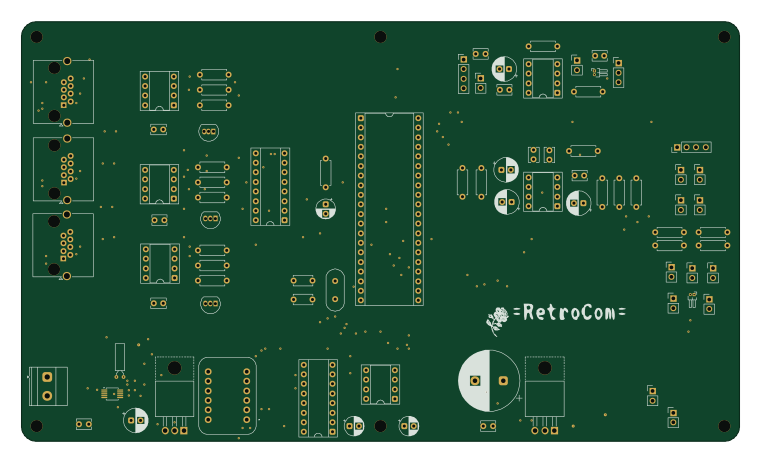
Similar boards
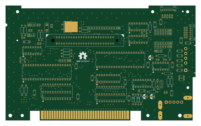
OpenTendo
Redherring32
196.3 × 118.7 mm93 parts2LTAPR-OHL-1.0850
MCL86jr
MicroCoreLabs
56.1 × 57.1 mm66 parts4LNo license532
24pin flex interposer
Wren6991
29 × 32 mm3 parts2LNo license508
Sram dev board
50 × 50 mm12 parts2LNo license508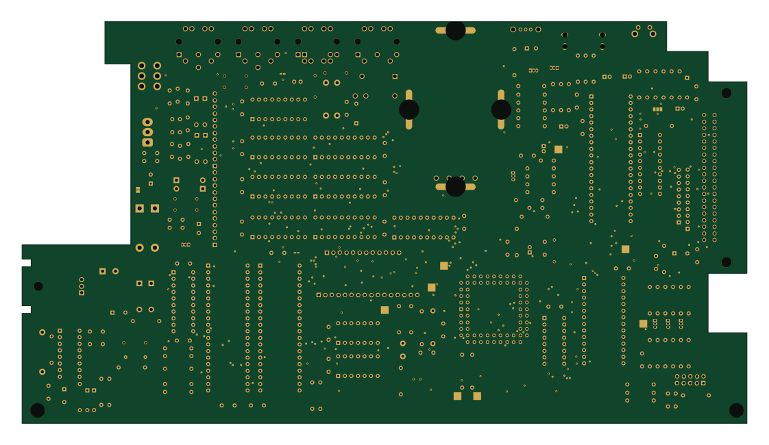
TRS-80 Color Computer 3
baldengineer
280 × 155.3 mm204 parts2LCC-BY-4.0442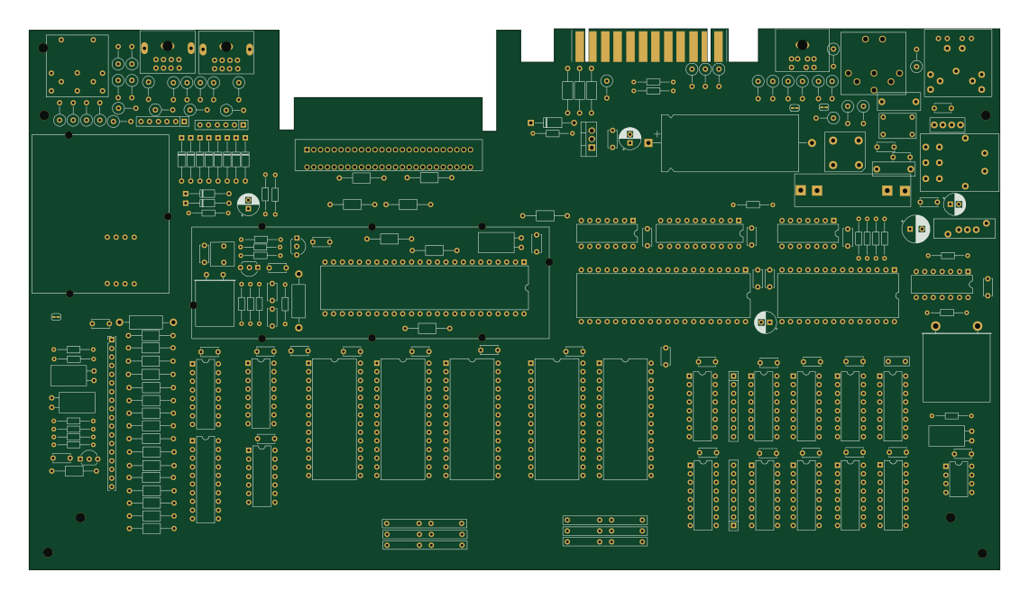
Commodore Plus 4
284.7 × 158.9 mm212 parts2LCC-BY-4.0442