
Main

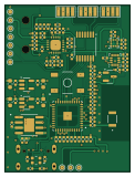
About the Main PCB
Main is an open source RP2040/RP2350 PCB design by SonDinh23, published on GitHub under the GPL-3.0 license. It is a 4-layer board measuring 30 × 40 mm, with 116 components from 45 distinct parts.
Its main chip is the ESP32-PICO-V3-02, from the RP2040/RP2350 family. Other key parts include the CP2102N-AXX-XQFN28, LSM6DSL, MCP3204, XC6220B331MR and TP4056. By type, the board carries 49 capacitors, 45 resistors, 12 ICs, 3 transistors, 3 connectors and 1 antenna.
It belongs with the sensors, power & battery and iot & wireless designs in this gallery.
From the project
VEDC is a wearable biomedical reference design that blends EMG, ECG, and PPG sensing in a developer-friendly package.
Reference hub for every PCB in the VEDC stack. Each section collects the essential narrative (what the board does), quick specs, manufacturing artifacts, bring-up notes and a gallery that matches the files committed to this repo.
- Use forward slashes / in Markdown image paths; all current links are relative to this README. - Example snippet: ``. - GitHub renders images only after the corresponding PNG/SVG files are committed and pushed. - Need a different layout (per-board README, thumbnail sizes, PDF gallery)? Let me know and I can spin up that structure quickly.
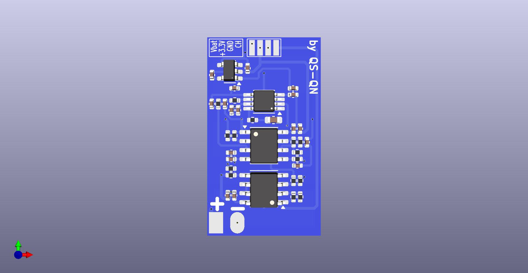
Main components on the Main
Main bill of materials (BOM)
116 components, 45 distinct parts — part numbers from the project's BOM.
| Qty | Part | Footprint | Refs |
|---|---|---|---|
| 1 | ESP32-PICO-V3-02 | XCVR_ESP32-PICO-V3-02 | U1 |
| 1 | CP2102N-AXX-XQFN28 CP2102N-Axx-xQFN28 | QFN-28-1EP_5x5mm_P0.5mm_EP3.35x3.35mm | U2 |
| 1 | LSM6DSL | LGA-14_3x2.5mm_P0.5mm_LayoutBorder3x4y | U3 |
| 1 | MCP3204 | TSSOP-14_4.4x5mm_P0.65mm | U4 |
| 2 | XC6220B331MR | SOT-23-5 | U5, U15 |
| 1 | TP4056 | SOP127P600X175-9N | U6 |
| 1 | LIS3MDL | LGA-12_2x2mm_P0.5mm | U7 |
| 3 | Pad 4 | Pad 4 | U8, U9, U10 |
| 1 | AD8232 | LFCSP_20 | U13 |
| 2 | SS8050 | SOT-23 | Q1, Q2 |
| 1 | MMBT2222A | SOT-23 | Q3 |
| 1 | USB_C_RECEPTACLE_USB2.0_16P USB_C_Receptacle_USB2.0_16P | USB_C_Receptacle_GCT_USB4105-xx-A_16P_TopMnt_Horizontal | J1 |
| 1 | SJ2-3593D-SMT SJ2-3593D-SMT-TR | CUI_SJ2-3593D-SMT-TR | J2 |
| 1 | SM05B-SRSS-TB_LF__SN_ | JST_SM05B-SRSS-TB_LF__SN_ | J3 |
| 1 | RFECA3216060A1T | ANT_16060A1T_WAL | AE1 |
| 1 | Buzzer | Buzzer_Murata_PKMCS0909E | BZ1 |
| 1 | TL3342F160QG | SW_TL3342F160QG | S1 |
| 1 | WS2812B2020 | LED_WS2812B2020 | D2 |
| 5 | 1UF 1uF | C_0402_1005Metric | C1, C22, C24, C26, C28 |
| 15 | 4.7UF 4.7uF | C_0402_1005Metric | C2, C4, C6, C8, C10, C12, C14, C16 +7 |
Show 25 more
| Qty | Part | Footprint | Refs |
|---|---|---|---|
| 17 | 100NF 100nF | C_0402_1005Metric | C3, C5, C7, C9, C11, C13, C15, C17 +9 |
| 2 | 10NF 10nF | C_0402_1005Metric | C20, C46 |
| 4 | 22UF 22uF | C_0603_1608Metric | C21, C23, C25, C27 |
| 1 | 1NF 1nF | C_0402_1005Metric | C44 |
| 2 | 0.33UF 0.33uF | C_0402_1005Metric | C45, C48 |
| 1 | 1.5NF 1.5nF | C_0402_1005Metric | C47 |
| 2 | 0.1UF 0.1uF | C_0402_1005Metric | C49, C50 |
| 4 | 0R | C_0402_1005Metric | R1, R3, R6, R16 |
| 11 | 10K | C_0402_1005Metric | R2, R10, R11, R12, R13, R14, R15, R22 +3 |
| 2 | 5.1K | C_0402_1005Metric | R4, R5 |
| 1 | 4.7K | C_0402_1005Metric | R7 |
| 1 | 24K | C_0402_1005Metric | R8 |
| 1 | 47K | C_0402_1005Metric | R9 |
| 1 | 3K | C_0402_1005Metric | R17 |
| 3 | 200K | C_0402_1005Metric | R18, R19, R20 |
| 1 | 300K | C_0402_1005Metric | R21 |
| 2 | 0 | C_0402_1005Metric | R25, R43 |
| 2 | DNP | C_0402_1005Metric | R26, R44 |
| 5 | 1M | C_0402_1005Metric | R27, R30, R34, R35, R37 |
| 2 | 1K | C_0402_1005Metric | R28, R29 |
| 2 | 180K | C_0402_1005Metric | R31, R32 |
| 1 | 360K | C_0402_1005Metric | R33 |
| 1 | 100K | C_0402_1005Metric | R36 |
| 4 | 10M | C_0402_1005Metric | R38, R39, R41, R42 |
| 1 | 1.4M | C_0402_1005Metric | R40 |
Main design files
The KiCad project lives in the SonDinh23/VEDC repository on GitHub; these links point at the commit this page was built from.
Main: common questions
What microcontroller does the Main use?
The Main is built around the ESP32-PICO-V3-02, from the RP2040/RP2350 family.
How big is the Main PCB?
The Main measures 30 × 40 mm, has 4 copper layers and is 1 mm thick.
How many components are on the Main?
116 components, from 45 distinct parts, with part numbers taken from the project's own BOM. The full bill of materials is listed on this page.
Where can I download the Main design files?
From the SonDinh23/VEDC repository on GitHub, which has the KiCad layout, the schematic and the BOM; the links under Design files point to each one.
Can I use the Main design in my own project?
Yes, under the terms of its GPL-3.0 license, which SonDinh23 chose for the repository.
Can I test firmware for the Main without the hardware?
Yes. HardLabs builds a simulation of the board from its netlist and BOM, so you can run and debug RP2040/RP2350 firmware against it before you order a PCB.
More boards in VEDC

Similar boards
 RP2040/RP2350
OSO-BOOK-C1
joeycastillo
85 × 115 mm29 parts2LCC-BY-SA-4.08.1k RP2040/RP2350
Corne cherry
foostan
277.2 × 107.5 mm164 parts2LCC-BY-4.07.7k RP2040/RP2350
Corne chocolate
277.2 × 107.5 mm164 parts2LCC-BY-4.07.7k RP2040/RP2350
Jitx design
gusmanb
55.5 × 65 mm26 parts4LGPL-3.05.0k RP2040/RP2350
LogicAnalyzer
57 × 55.2 mm6 parts2LGPL-3.05.0k RP2040/RP2350
Main
google
98 × 71 mm102 parts2LApache-2.02.9k