
Analog

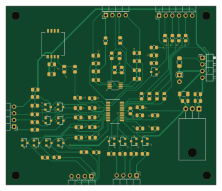
About the Analog PCB
Analog is an open source PCB design by via, published on GitHub. It is a 2-layer board measuring 80.2 × 68 mm, with 88 components from 35 distinct parts.
Other key parts include the LM2940 and TC442XA. By type, the board carries 34 resistors, 29 capacitors, 14 diodes, 6 connectors, 4 ICs and 1 fuse.
It belongs with the sensors designs in this gallery.
From the project
ViaEMS PCB Designs
In order of creation... ## Analog V1 - Analog/ADC Core board based on a DIP TLC2543 - All throughhole - Dedicated 5V supply - 4 Thermistor inputs - Inputs for EGO, BRV, MAP, TPS - 5 Spares
Do not use because: - 3v supply for CAN doesn't work at all - the FETs without gate drivers has poor performance from a 3.3 V microcontroller - No VR inputs
Shouldn't be used anymore, but really only because the outputs chosen for test trigger vs real triggers are different in firmware. The board can be used again with some minor tweaks (and I have used this board for years)
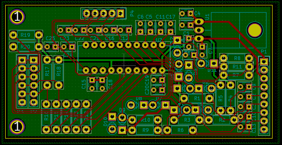
Main components on the Analog
Analog bill of materials (BOM)
88 components, 35 distinct parts — part numbers from the project's BOM.
| Qty | Part | Footprint | Refs |
|---|---|---|---|
| 1 | LM2940 MAX11632 | QSOP-24_3.9x8.7mm_P0.635mm | U1 |
| 1 | TC442XA LM2940 | TO-220-3_Horizontal_TabDown | U2 |
| 1 | TC442XA MCP6002-xSN | MSOP-8_3x3mm_P0.65mm | U3 |
| 1 | TC442XA MPXA6400A | Freescale_98ARH99089A | U4 |
| 1 | CONN_02X08_COUNTER_CLOCKWISE SPARE1 | PinHeader_1x04_P2.54mm_Horizontal | J1 |
| 1 | CONN_01X02 SPARE2 | PinHeader_1x04_P2.54mm_Horizontal | J2 |
| 1 | CONN_01X03 MAIN | PinHeader_1x04_P2.54mm_Horizontal | J3 |
| 1 | CONN_01X04 KNOCK | PinHeader_1x04_P2.54mm_Horizontal | J4 |
| 1 | CONN_01X02 POWER | PinHeader_1x04_P2.54mm_Horizontal | J5 |
| 1 | CONN_01X06 | PinHeader_1x06_P2.54mm_Horizontal | P1 |
| 1 | 500 mA | Fuse_1206_3216Metric_Pad1.42x1.75mm_HandSolder | F1 |
| 4 | BAT54S | SOT-23 | D1, D9, D13, D14 |
| 1 | ZEN056V115A24LS BAT54S | SOT-23 | D2 |
| 8 | BAT54S | SOT-23 | D3, D5, D6, D7, D8, D10, D11, D12 |
| 1 | 5.4 V | D_A-405_P2.54mm_Vertical_AnodeUp | D4 |
| 1 | 10 uF | C_0805_2012Metric_Pad1.18x1.45mm_HandSolder | C1 |
| 10 | 0.47 uF | C_0805_2012Metric_Pad1.18x1.45mm_HandSolder | C2, C14, C18, C21, C22, C23, C26, C27 +2 |
| 5 | 0.1 uF | C_0805_2012Metric_Pad1.18x1.45mm_HandSolder | C3, C12, C13, C17, C25 |
| 5 | 1 uF | C_0805_2012Metric_Pad1.18x1.45mm_HandSolder | C4, C11, C15, C16, C19 |
| 5 | 1UF 0.1 uF | C_0805_2012Metric_Pad1.18x1.45mm_HandSolder | C5, C6, C7, C9, C10 |
Show 15 more
| Qty | Part | Footprint | Refs |
|---|---|---|---|
| 1 | 1UF 47 uF | C_1206_3216Metric_Pad1.33x1.80mm_HandSolder | C8 |
| 1 | 0.01 uF | C_0805_2012Metric_Pad1.18x1.45mm_HandSolder | C20 |
| 1 | 0.33 uF | C_0805_2012Metric_Pad1.18x1.45mm_HandSolder | C24 |
| 9 | 100K 220 | R_0805_2012Metric_Pad1.20x1.40mm_HandSolder | R1, R3, R11, R29, R30, R31, R32, R33 +1 |
| 2 | 100K 2.49k | R_0805_2012Metric_Pad1.20x1.40mm_HandSolder | R2, R4 |
| 5 | 220 | R_0805_2012Metric_Pad1.20x1.40mm_HandSolder | R5, R10, R24, R27, R28 |
| 4 | 1000 | R_0805_2012Metric_Pad1.20x1.40mm_HandSolder | R6, R7, R22, R23 |
| 2 | 330 | R_0805_2012Metric_Pad1.20x1.40mm_HandSolder | R8, R9 |
| 2 | 100K 120 | R_0805_2012Metric_Pad1.20x1.40mm_HandSolder | R12, R13 |
| 3 | 100K 100 | R_0805_2012Metric_Pad1.20x1.40mm_HandSolder | R14, R15, R16 |
| 1 | 150 100 | R_0805_2012Metric_Pad1.20x1.40mm_HandSolder | R17 |
| 3 | 150 10k | R_0805_2012Metric_Pad1.20x1.40mm_HandSolder | R18, R19, R20 |
| 1 | 10k | R_0805_2012Metric_Pad1.20x1.40mm_HandSolder | R21 |
| 1 | 3.9k | R_0805_2012Metric_Pad1.20x1.40mm_HandSolder | R25 |
| 1 | 1k | R_0805_2012Metric_Pad1.20x1.40mm_HandSolder | R26 |
Analog design files
The KiCad project lives in the via/viaems-boards repository on GitHub; these links point at the commit this page was built from.
Analog: common questions
How big is the Analog PCB?
The Analog measures 80.2 × 68 mm, has 2 copper layers and is 1.6 mm thick.
How many components are on the Analog?
88 components, from 35 distinct parts, with part numbers taken from the project's own BOM. The full bill of materials is listed on this page.
Where can I download the Analog design files?
From the via/viaems-boards repository on GitHub, which has the KiCad layout, the schematic and the BOM; the links under Design files point to each one.
Can I use the Analog design in my own project?
The repository has no license, so all rights stay with via. Use it as a reference, and ask the author before reusing the design.
More boards in viaems-boards
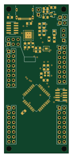
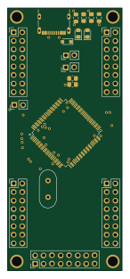
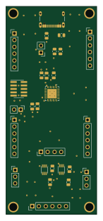
Similar boards
Sensor smd
scottbez1
40 × 20 mm5 parts2LApache-2.04.2k
Sensors
StuckAtPrototype
15.2 × 9 mm14 parts4LApache-2.03.8k
Microphone
Mentra-Community
5.5 × 6.1 mm6 parts2LMIT1.2k
TemperaturePCB PANEL
stuartpittaway
116 × 75.5 mm178 parts2LCC-BY-NC-4.01.1k
Pots
shanteacontrols
390 × 93 mm75 parts2LApache-2.0956
USB
52 × 12.6 mm6 parts2LApache-2.0956