
Node v7 0 0

About the Node v7 0 0 PCB
Node v7 0 0 is an open source RP2040/RP2350 PCB design by VTC-WISDOM, published on GitHub under the CERN-OHL-W-2.0 license. It is a 6-layer board, with 81 components from 39 distinct parts.
Its main chip is the RP2040, from the RP2040/RP2350 family. Other key parts include the USBLC6-2SC6, AP2112K-3.3, RFM69HCW, PCF8523T and SP3485EN. By type, the board carries 38 capacitors, 15 resistors, 9 ICs, 9 connectors, 2 switches and 2 diodes.
It belongs with the rf & radio designs in this gallery, and the repository also holds 4 earlier revisions of it.
From the project
Schematic/PCB designs for WiSDOM nodes, also includes a few other related hardware projects
changes: - removed 5v regulator - changed rp2040 xtal to the recommended part due to availability - changed the sim card slot due to availability - reviewed other parts and made changes to ensure full availability from both JLC and Digikey - changed footprints over to JLC library footprints - major layout changes- pin headers now broken out in two halves, etc - look at the pcb for a full description - removed jst connectors (evil) and replaced them with barrel jacks - mounting holes now m2.5 instead of m2
Main components on the Node v7 0 0
Node v7 0 0 bill of materials (BOM)
81 components, 39 distinct parts.
| Qty | Part | Footprint | Refs |
|---|---|---|---|
| 1 | RP2040 | QFN-56-1EP_7x7mm_P0.4mm_EP3.2x3.2mm_ThermalVias | U1 |
| 1 | USBLC6-2SC6 | SOT-23-6_L2.9-W1.6-P0.95-LS2.8-BL | U2 |
| 1 | AP2112K-3.3 | SOT-23-5_L3.0-W1.7-P0.95-LS2.8-BL | U3 |
| 1 | RFM69HCW | HOPERF_RFM9XW_SMD | U6 |
| 1 | PCF8523T | SOIC-8_3.9x4.9mm_P1.27mm | U7 |
| 1 | SP3485EN MaxLinear | SOIC-8_L5.0-W4.0-P1.27-LS6.0-BL | U8 |
| 1 | SIM7080G | XCVR_SIM7080G | U9 |
| 1 | CAT24M01W | SOIC-8_3.9x4.9mm_P1.27mm | U12 |
| 1 | W25Q128 Winbond Elec | SOIC-8_L5.3-W5.3-P1.27-LS8.0-BL | U14 |
| 1 | DMG2301L | D_SOT-23 | Q1 |
| 1 | ABM8-272-T3 | CRYSTAL-SMD_4P-L3.2-W2.5-BL | Y1 |
| 1 | 786463001 | 78646-3001_MOL | J1 |
| 3 | U.FL | IPEX-SMD_BWIPX-1-001E | J2, J6, J9 |
| 2 | Conn_01x10 | PinHeader_1x10_P2.54mm_Vertical | J4, J5 |
| 2 | Barrel_Jack_Switch | PJ-007 | J7, J11 |
| 1 | Connector, USB-TYPE-C-16P | TYPE-C-SMD_HX-TYPE-C-16PIN | J10 |
| 1 | Polyfuse | F1 | |
| 2 | PTS636 SM50J SMTR LFS | SW_PTS636_CNK | SW2, SW3 |
| 1 | Thermistor_NTC | R_0402 | TH1 |
| 1 | SC32S-7PF20PPM | XTAL_SC32S-7PF20PPM_EPS | XTAL1 |
Show 19 more
| Qty | Part | Footprint | Refs |
|---|---|---|---|
| 1 | SS14 MDD(Microdiode Electronics) | D_SMA | D2 |
| 1 | 1SMB5921BT3G | D_SMB | D3 |
| 1 | 68n | L_0402 | L1 |
| 16 | 0.1u Samsung Electro-Mechanics | C_0402 | C1, C2, C3, C4, C5, C6, C7, C10 +8 |
| 8 | 10u Samsung Electro-Mechanics | C_0805 | C13, C15, C18, C23, C24, C29, C45, C47 |
| 3 | 1u Samsung Electro-Mechanics | C_0805 | C14, C16, C41 |
| 2 | 15p FH(Guangdong Fenghua Advanced Tech) | C_0402 | C19, C20 |
| 1 | 3.3u | C_0805 | C26 |
| 4 | 33p FH(Guangdong Fenghua Advanced Tech) | C_0402 | C34, C35, C36, C43 |
| 3 | 100u Samsung Electro-Mechanics | C_0805 | C39, C40, C42 |
| 1 | 100n Samsung Electro-Mechanics | C_0402 | C48 |
| 2 | 27.4 UNI-ROYAL(Uniroyal Elec) | R_0603 | R1, R2 |
| 2 | 5.1k | R_0603 | R3, R4 |
| 1 | 1k UNI-ROYAL(Uniroyal Elec) | R_0402 | R5 |
| 1 | 10k UNI-ROYAL(Uniroyal Elec) | R_0603 | R8 |
| 2 | 10k UNI-ROYAL(Uniroyal Elec) | R_0805 | R9, R10 |
| 4 | 22 UNI-ROYAL(Uniroyal Elec) | R_0402 | R11, R12, R13, R16 |
| 2 | 470k UNI-ROYAL(Uniroyal Elec) | R_0603 | R17, R18 |
| 1 | 10k | R_0402 | R20 |
Node v7 0 0 design files
The KiCad project lives in the VTC-WISDOM/node_hardware repository on GitHub; these links point at the commit this page was built from.
Node v7 0 0: common questions
What microcontroller does the Node v7 0 0 use?
The Node v7 0 0 is built around the RP2040, from the RP2040/RP2350 family.
How big is the Node v7 0 0 PCB?
The Node v7 0 0 has 6 copper layers and is 1.6 mm thick.
How many components are on the Node v7 0 0?
81 components, from 39 distinct parts. The full bill of materials is listed on this page.
Where can I download the Node v7 0 0 design files?
From the VTC-WISDOM/node_hardware repository on GitHub, which has the KiCad layout and the schematic; the links under Design files point to each one.
Can I use the Node v7 0 0 design in my own project?
Yes, under the terms of its CERN-OHL-W-2.0 license, which VTC-WISDOM chose for the repository.
Can I test firmware for the Node v7 0 0 without the hardware?
Yes. HardLabs builds a simulation of the board from its netlist and BOM, so you can run and debug RP2040/RP2350 firmware against it before you order a PCB.
More boards in node_hardware
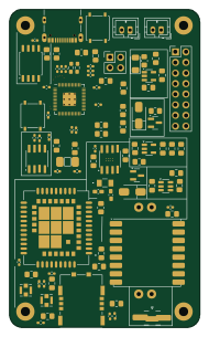
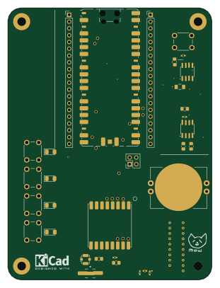
Earlier revisions in the repo: node_v6_2_0, node_v6_1_0, node_v6_0_0, node_v5_0_0
Similar boards
 RP2040/RP2350
Open Book Abridged Edition
joeycastillo
85 × 115 mm29 parts2LCC-BY-SA-4.08.1k RP2040/RP2350
Corne
foostan
277.2 × 107.5 mm164 parts2LCC-BY-4.07.7k RP2040/RP2350
Corne
277.2 × 107.5 mm164 parts2LCC-BY-4.07.7k RP2040/RP2350
LogicAnalyzer
gusmanb
57 × 55.2 mm6 parts2LGPL-3.05.0k RP2040/RP2350
Jitx design
55.5 × 65 mm26 parts4LGPL-3.05.0k RP2040/RP2350
Pro V2
kata0510
290.1 × 130 mm270 parts2LMIT2.3k