
Autofeedermod

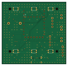
About the Autofeedermod PCB
Autofeedermod is an open source ESP32 PCB design by wabolabs, published on GitHub under the CERN-OHL-W-2.0 license. It is a 4-layer board measuring 56 × 54 mm, with 39 components from 28 distinct parts.
Its main chip is the ESP32-C6-Zero, from the ESP32 family. Other key parts include the TP4056, DW01A, TPS63031DSKR, SN65HVD230 and FS8205A. By type, the board carries 7 resistors, 6 ICs, 6 switches, 6 capacitors, 3 connectors and 2 LEDs.
It belongs with the iot & wireless, power & battery and displays & leds designs in this gallery.
From the project
ESP32-C6 based chicken feed dispenser controller with Matter, CAN bus, and 18650 battery
Drop-in PCB replacement for a timed chicken feed dispenser. ESP32-C6 based with Matter/ESPHome, local standalone operation, motor control, CAN bus, RTC timekeeping, and optional GPS sync.
- MCU: ESP32-C6-Zero (Matter, WiFi 6, Thread, BLE 5) — socketed via 2×9 2.54mm headers + 7 pogo pins - Display: SSD1306 128×64 SPI OLED with full menu system (status, schedules, settings, GPS, manual feed) - Motor: DRV8871 H-bridge for 4VDC auger motor - Power: 18650 Li-ion with TP4056 charger + DW01A/FS8205A battery protection + TPS63031 buck-boost to 3.3V - RTC: DS3231 module (I2C) with CR2032 backup for…
Main components on the Autofeedermod
Autofeedermod bill of materials (BOM)
39 components, 28 distinct parts — part numbers from the project's BOM.
| Qty | Part | Footprint | Refs |
|---|---|---|---|
| 1 | ESP32-C6-Zero | ESP32_C6_Zero | U1 |
| 1 | TP4056 | SOIC-8_3.9x4.9mm_P1.27mm | U2 |
| 1 | DW01A | SOT-23-6_Handsoldering | U3 |
| 1 | TPS63031DSKR | WSON-10-1EP_2.5x2.5mm_P0.5mm_EP1.2x2mm | U4 |
| 1 | SN65HVD230 | SOIC-8_3.9x4.9mm_P1.27mm | U6 |
| 1 | FS8205A | SOT-23-6_Handsoldering | U8 |
| 1 | BATTERY | JST_XH_B2B-XH-A_1x02_P2.50mm_Vertical | J1 |
| 1 | USB-C | USB_C_Receptacle_HRO_TYPE-C-31-M-12 | J3 |
| 1 | DBG | PinHeader_1x04_P2.54mm_Vertical | J4 |
| 1 | 500mA | Fuse_1812_4532Metric | F1 |
| 1 | GPS | PinHeader_1x04_P2.54mm_Vertical | J_GPS1 |
| 1 | MOTOR_CTRL | JST_XH_B2B-XH-A_1x02_P2.50mm_Vertical | J_MOTOR_CTRL1 |
| 1 | MOTOR_PWR | JST_XH_B2B-XH-A_1x02_P2.50mm_Vertical | J_MOTOR_PWR1 |
| 1 | DS3231 | PinHeader_1x04_P2.54mm_Vertical | J_RTC1 |
| 2 | 5.1k | R_0603_1608Metric | R_CC1, R_CC2 |
| 6 | Alps SKRPADE010 | SW_Push_1P1T_NO_CK_KMR2 | SW1_POWER1, SW2_TIMER1, SW3_MANUAL1, SW4_SETTINGS1, SW5_UP1, SW6_DOWN1 |
| 1 | OLED_SSD1306 | OLED_1.3in_SSD1306_SPI | DISP1 |
| 1 | RED | LED_0603_1608Metric | LED_CHG1 |
| 1 | 1N5817 | D_DO-41_SOD81_P10.16mm_Horizontal | D1 |
| 1 | 4.7uH | L_0805_2012Metric | L1 |
Show 8 more
| Qty | Part | Footprint | Refs |
|---|---|---|---|
| 3 | 100nF | C_0603_1608Metric | C1, C3, C6 |
| 2 | 10uF | C_0805_2012Metric | C2, C4 |
| 1 | 22uF | C_0805_2012Metric | C5 |
| 1 | 1.2k | R_0603_1608Metric | R2_C1 |
| 2 | 47k | R_0603_1608Metric | R3, R4 |
| 1 | 120R | R_0603_1608Metric | R5 |
| 2 | 1k | R_0603_1608Metric | R6, R10 |
| 1 | 10k | R_0603_1608Metric | R13 |
Autofeedermod design files
The KiCad project lives in the wabolabs/autofeedermod repository on GitHub; these links point at the commit this page was built from.
Autofeedermod: common questions
What microcontroller does the Autofeedermod use?
The Autofeedermod is built around the ESP32-C6-Zero, from the ESP32 family.
How big is the Autofeedermod PCB?
The Autofeedermod measures 56 × 54 mm, has 4 copper layers and is 1.6 mm thick.
How many components are on the Autofeedermod?
39 components, from 28 distinct parts, with part numbers taken from the project's own BOM. The full bill of materials is listed on this page.
Where can I download the Autofeedermod design files?
From the wabolabs/autofeedermod repository on GitHub, which has the KiCad layout, the schematic and the BOM; the links under Design files point to each one.
Can I use the Autofeedermod design in my own project?
Yes, under the terms of its CERN-OHL-W-2.0 license, which wabolabs chose for the repository.
Can I test firmware for the Autofeedermod without the hardware?
Yes. HardLabs builds a simulation of the board from its netlist and BOM, so you can run and debug ESP32 firmware against it before you order a PCB.
Similar boards
 ESP32
ESP32Open Book Abridged Edition
joeycastillo
85 × 115 mm65 parts2LCC-BY-SA-4.08.1k ESP32
ESP32Esp32 minimal
atopile
36.2 × 26.8 mm20 parts2LMIT4.0k ESP32
ESP32Badge
56.3 × 39 mm239 parts4LMIT4.0k ESP32
ESP32Controller
StuckAtPrototype
29 × 74 mm58 parts4LApache-2.03.8k ESP32
ESP32Racer
36 × 50.2 mm70 parts4LApache-2.03.8k ESP32
ESP32Bitaxe
skot
56.5 × 99.8 mm86 parts4LCERN-OHL-S-2.01.4k