
LoRaModem

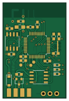
About the LoRaModem PCB
LoRaModem is an open source STM32 PCB design by wangyeee, published on GitHub under the BSD-3-Clause license. It is a 2-layer board measuring 24 × 36 mm, with 48 components from 31 distinct parts.
Its main chip is the STM32F103CBTx, from the STM32 family. Other key parts include the Ra-02, W25X40, SPX3819, TJA1050 and 74AHC1G86. By type, the board carries 17 capacitors, 9 diodes, 8 resistors, 6 ICs, 3 connectors and 3 test points.
It belongs with the robotics & motion and rf & radio designs in this gallery.
From the project
Collections of hardware design related to my drone project.
1. Serial port (Full-duplex): This port connects to a dedicate GPS receiver, or it can read GPS messages from standard telemetry (such as MavLink) port from an autopilot. 2. CAN bus: This is used to talk to the autopilot, as well as other devices on the same bus. Currently there is no plan for software support. 3. Serial port (Half-duplex): This is a TX only serial port, with built-in inverter which can be used to generate S.Bus signals. It could be used to control external severos for custom purposes. 4. Flash memory: The onboard flash chip can be used to store information like device ID, as…
Main components on the LoRaModem
LoRaModem bill of materials (BOM)
48 components, 31 distinct parts.
| Qty | Part | Footprint | Refs |
|---|---|---|---|
| 1 | Ra-02 | RA0x-LCC16 | U1 |
| 1 | W25X40 | SOIC-8_3.9x4.9mm_Pitch1.27mm | U2 |
| 1 | STM32F103CBTx | LQFP-48_7x7mm_Pitch0.5mm | U3 |
| 1 | SPX3819 | SOT-23-5 | U4 |
| 1 | TJA1050 | SOIC-8_3.9x4.9mm_Pitch1.27mm | U5 |
| 1 | 74AHC1G86 | SOT-23-5 | U6 |
| 1 | 8MHz | CERALOCK-CSTCE | Y1 |
| 2 | CONN_01X04 | M04_SMD | J1, J3 |
| 1 | CONN_01X03 | M03 | J2 |
| 1 | Jumper | JUMPER_SMALL | JP1 |
| 1 | SWDIO | TESTPAD_SMALL | TP1 |
| 1 | SWCLK | TESTPAD_SMALL | TP2 |
| 1 | SWO | TESTPAD_SMALL | TP3 |
| 3 | 1A | D_SOD-123 | D1, D8, D9 |
| 1 | PESD3V3 | SOT-23 | D2 |
| 1 | PESD3V3 | D_SOD-323_HandSoldering | D3 |
| 1 | RED | LED_0603 | D4 |
| 1 | BLUE | LED_0603 | D5 |
| 1 | GREEN | LED_0603 | D6 |
| 1 | PESDCAN | SOT-23 | D7 |
Show 11 more
| Qty | Part | Footprint | Refs |
|---|---|---|---|
| 10 | 100nF | C_0603_HandSoldering | C1, C3, C4, C8, C10, C11, C12, C13 +2 |
| 1 | 22uF | C_0805_HandSoldering | C2 |
| 2 | 2.2uF | C_0603_HandSoldering | C5, C7 |
| 2 | 10nF | C_0603_HandSoldering | C6, C16 |
| 1 | 10uF | C_0603_HandSoldering | C9 |
| 1 | 1uF | C_0603_HandSoldering | C14 |
| 1 | 47K | R_0603_HandSoldering | R1 |
| 2 | 10K | R_0603_HandSoldering | R2, R3 |
| 1 | 120 | R_0603_HandSoldering | R4 |
| 3 | 470 | R_0603_HandSoldering | R5, R6, R7 |
| 1 | 1.5K | R_0603_HandSoldering | R8 |
LoRaModem design files
The KiCad project lives in the wangyeee/OpenHardware repository on GitHub; these links point at the commit this page was built from.
LoRaModem: common questions
What microcontroller does the LoRaModem use?
The LoRaModem is built around the STM32F103CBTx, from the STM32 family.
How big is the LoRaModem PCB?
The LoRaModem measures 24 × 36 mm, has 2 copper layers and is 1.6 mm thick.
How many components are on the LoRaModem?
48 components, from 31 distinct parts. The full bill of materials is listed on this page.
Where can I download the LoRaModem design files?
From the wangyeee/OpenHardware repository on GitHub, which has the KiCad layout; the links under Design files point to each one.
Can I use the LoRaModem design in my own project?
Yes, under the terms of its BSD-3-Clause license, which wangyeee chose for the repository.
Can I test firmware for the LoRaModem without the hardware?
Yes. HardLabs builds a simulation of the board from its netlist and BOM, so you can run and debug STM32 firmware against it before you order a PCB.
More boards in OpenHardware
 STM32
STM32SimpleFC G
42 × 50 mm130 parts4LBSD-3-Clause9 STM32
STM32SimpleFCv2
42 × 50 mm119 parts4LBSD-3-Clause9 STM32
STM32Tinyfc core
36 × 44 mm103 parts4LBSD-3-Clause9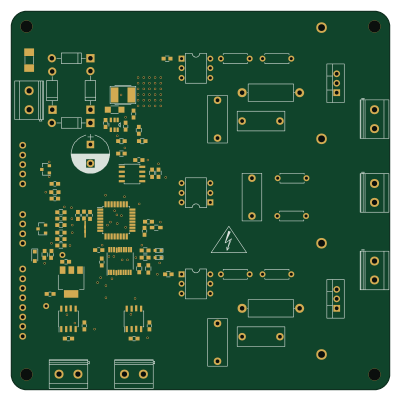 AVR/Arduino
ReflowOvenController
100 × 100 mm97 parts2LBSD-3-Clause9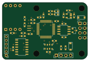 STM32
STM32AirSeneor
45 × 30 mm39 parts2LBSD-3-Clause9
TinyBEC
23 × 18 mm16 parts2LBSD-3-Clause9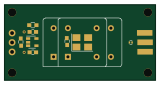
MultiOsc
40 × 20 mm12 parts2LBSD-3-Clause9
Similar boards
 STM32
STM32LumenPnP Motherboard
opulo-inc
149 × 95 mm296 parts4LCC-BY-SA-4.03.7k STM32
STM32AxxSolder
AxxAxx
39 × 82.5 mm122 parts2LGPL-3.01.7k STM32
STM32AIOC
skuep
21 × 31.5 mm47 parts2LMIT1.4k STM32
STM32Ferris
pierrechevalier83
208.8 × 86.8 mm102 parts2LSHL-2.11.3k STM32
STM32176 pin board
rusefi
61.8 × 73.2 mm76 parts2LGPL-3.01.2k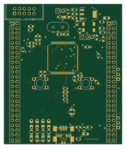 STM32
STM32Brain board STM32F407
61.8 × 73.2 mm69 parts2LGPL-3.01.2k