
UEFI-v6.x

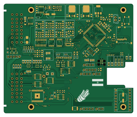
About the UEFI-v6.x PCB
UEFI-v6.x is an open source STM32 PCB design by Churrosoft, published on GitHub. It is a 4-layer board measuring 116.5 × 98 mm, with 193 components from 71 distinct parts.
Its main chip is the MCZ33810EK, from the STM32 family. Other key parts include the TC4424AVOA, TPL7407LAPWR, LMV324, AMS1117-3.3 and SP720ABTG. By type, the board carries 72 resistors, 55 capacitors, 32 diodes, 19 ICs, 7 transistors and 3 connectors.
From the project
Speeduino compatible board, x4 ignition channels, x4 injection channels, 2&4 wire IAC
Main components on the UEFI-v6.x
UEFI-v6.x bill of materials (BOM)
193 components, 71 distinct parts.
| Qty | Part | Footprint | Refs |
|---|---|---|---|
| 1 | MCZ33810EK | SOP65P1030X245-33N | U1 |
| 2 | TC4424AVOA TC4424A | SOIC-8_3.9x4.9mm_P1.27mm | U2, U3 |
| 1 | TPL7407LAPWR | TSSOP-16_4.4x5mm_P0.65mm | U5 |
| 2 | LMV324 | TSSOP-14_4.4x5mm_P0.65mm | U6, U7 |
| 1 | AMS1117-3.3 | SOT-223-3_TabPin2 | U8 |
| 1 | SP720ABTG | SOP-16_3.9x9.9mm_P1.27mm | U9 |
| 1 | BMP280 | Bosch_LGA-8_2x2.5mm_P0.65mm_ClockwisePinNumbering | U10 |
| 2 | L78M05ABDT-TR | TO-252-2 | U11, U19 |
| 1 | LM74800 | LM74800 | U12 |
| 1 | STM32F407VGTx | LQFP-100_14x14mm_P0.5mm | U13 |
| 1 | TJA1051T-3 | SOP-8_3.9x4.9mm_P1.27mm | U14 |
| 1 | 25Q16 | SOIC-8_5.275x5.275mm_P1.27mm | U15 |
| 1 | REF3033 | SOT-23 | U16 |
| 1 | SRV05-4 | SOT-23-6 | U17 |
| 1 | VNLD5090-E VNLD5090 | SOIC-8_3.9x4.9mm_P1.27mm | U18 |
| 1 | ADXL343BCCZ-RL ADXL343 | LGA-14_3x5mm_P0.8mm_LayoutBorder1x6y | U21 |
| 4 | AO3400A | SOT-23 | Q1, Q2, Q6, Q7 |
| 1 | FDS6890A | SOP-8_3.9x4.9mm_P1.27mm | Q3 |
| 2 | SS8050 | SOT-23 | Q4, Q5 |
| 1 | 32.768kHz | Crystal_SMD_2012-2Pin_2.0x1.2mm | Y1 |
Show 51 more
| Qty | Part | Footprint | Refs |
|---|---|---|---|
| 1 | 25MHz | Crystal_SMD_3225-4Pin_3.2x2.5mm | Y2 |
| 1 | USB_B | USB_Mini-B_Tensility_54-00023_Vertical | J8 |
| 1 | Conn_01x04 | PinHeader_1x04_P2.54mm_Vertical | J14 |
| 1 | 47352-1001 | MOLEX_47352-1001 | J16 |
| 1 | 0ZCC0050FF2C Polyfuse | Fuse_1812_4532Metric | F1 |
| 2 | TestPoint_Alt | TestPoint_THTPad_1.0x1.0mm_Drill0.5mm | TP19, TP20 |
| 11 | SML-H12D8TT86C LED | LED_0805_2012Metric | D1, D4, D9, D12, D20, D21, D22, D23 +3 |
| 4 | LH R974-LP-1 LED | LED_0805_2012Metric | D2, D5, D7, D10 |
| 4 | 1N4448WX-TP 1N5819WS | D_SOD-323_HandSoldering | D3, D6, D8, D11 |
| 4 | 1N5819WS | D_SOD-323_HandSoldering | D16, D17, D18, D19 |
| 5 | 3.1v | D_SOD-323 | D27, D31, D32, D33, D34 |
| 1 | MM3Z24VT1G | D_SOD-323 | D28 |
| 2 | S110FA | D_SOD-123F | D29, D30 |
| 1 | SM6T33A | D_SMB | D35 |
| 7 | 0.01uF | C_0805_2012Metric | C1, C2, C3, C4, C5, C6, C7 |
| 1 | 4.7nF | C_0805_2012Metric | C8 |
| 19 | 100nF | C_0805_2012Metric | C9, C11, C12, C13, C14, C21, C22, C23 +11 |
| 2 | 100uF ±20% 35V | CP_Elec_6.3x7.7 | C10, C55 |
| 2 | 47nF | C_0603_1608Metric | C15, C48 |
| 6 | 0.22uF | C_0603_1608Metric | C16, C17, C18, C24, C27, C28 |
| 3 | CC0805KRX7R9BB104 0.1uF | C_0805_2012Metric | C19, C20, C25 |
| 2 | 2.2uF | C_0805_2012Metric | C26, C29 |
| 1 | 1uF | C_0805_2012Metric | C34 |
| 1 | 4.7uF | C_0805_2012Metric | C38 |
| 2 | 6.8pF | C_0805_2012Metric | C40, C41 |
| 2 | 15pF | C_0805_2012Metric | C42, C43 |
| 2 | 1u | C_0805_2012Metric | C44, C45 |
| 1 | 100n | C_0805_2012Metric | C46 |
| 3 | 0.1uF | C_0805_2012Metric | C51, C52, C53 |
| 1 | 10nF | C_0805_2012Metric | C54 |
| 8 | 10k | R_0603_1608Metric | R1, R2, R3, R4, R5, R10, R11, R27 |
| 10 | 1k | R_0603_1608Metric | R6, R9, R48, R49, R53, R59, R60, R61 +2 |
| 2 | 4.99K 1/2W | R_0805_2012Metric | R7, R8 |
| 2 | ERJ-6ENF4700V 470R | R_0805_2012Metric | R12, R13 |
| 3 | 2.49k +-1% | R_0603_1608Metric | R14, R15, R25 |
| 3 | RC0805FR-071KL 1k | R_0603_1608Metric | R16, R57, R58 |
| 8 | RC0805FR-07180KL 180k | R_0805_2012Metric | R17, R24, R33, R35, R36, R45, R46, R47 |
| 6 | 470R | R_0805_2012Metric | R18, R19, R20, R28, R29, R30 |
| 1 | RC0805FR-07604RL 604R | R_0805_2012Metric | R21 |
| 1 | RT0603BRD073K88L 3.88k | R_0603_1608Metric | R22 |
| 8 | ERJ-6ENF3483V 348k | R_0805_2012Metric | R23, R26, R39, R40, R41, R50, R51, R52 |
| 1 | 120R | R_1206_3216Metric | R31 |
| 7 | 4.7k | R_0603_1608Metric | R32, R34, R37, R38, R42, R43, R44 |
| 4 | 100k | R_0603_1608Metric | R54, R55, R56, R69 |
| 1 | 48.7k | R_0603_1608Metric | R62 |
| 1 | 42.2k | R_0603_1608Metric | R63 |
| 1 | 9.09k | R_0603_1608Metric | R64 |
| 1 | 3.48k | R_0603_1608Metric | R65 |
| 1 | 100R | R_0603_1608Metric | R67 |
| 2 | 1k | R_Array_Convex_4x0603 | RN1, RN2 |
| 1 | 47k | R_Array_Convex_4x0603 | RN3 |
UEFI-v6.x design files
The KiCad project lives in the Churrosoft/uEFI-v6.x repository on GitHub; these links point at the commit this page was built from.
- Layouthw_v1/hw_v1.kicad_pcb
- Schematichw_v1/hw_v1.kicad_sch
UEFI-v6.x: common questions
What microcontroller does the UEFI-v6.x use?
The UEFI-v6.x is built around the MCZ33810EK, from the STM32 family.
How big is the UEFI-v6.x PCB?
The UEFI-v6.x measures 116.5 × 98 mm, has 4 copper layers and is 1.6 mm thick.
How many components are on the UEFI-v6.x?
193 components, from 71 distinct parts. The full bill of materials is listed on this page.
Where can I download the UEFI-v6.x design files?
From the Churrosoft/uEFI-v6.x repository on GitHub, which has the KiCad layout and the schematic; the links under Design files point to each one.
Can I use the UEFI-v6.x design in my own project?
The repository has no license, so all rights stay with Churrosoft. Use it as a reference, and ask the author before reusing the design.
Can I test firmware for the UEFI-v6.x without the hardware?
Yes. HardLabs builds a simulation of the board from its netlist and BOM, so you can run and debug STM32 firmware against it before you order a PCB.
Similar boards
 STM32
LumenPnP Motherboard
opulo-inc
149 × 95 mm296 parts4LCC-BY-SA-4.03.7k STM32
Type g
google
169 × 30 mm24 parts2LApache-2.02.9k STM32
Main panel
234 × 84 mm26 parts4LApache-2.02.9k STM32
Base
52.3 × 52.3 mm36 parts2LApache-2.02.9k STM32
Type a
150 × 30 mm14 parts2LApache-2.02.9k STM32
Type c
188 × 30 mm17 parts2LApache-2.02.9k