
Smart Reciver Max Exp Pico

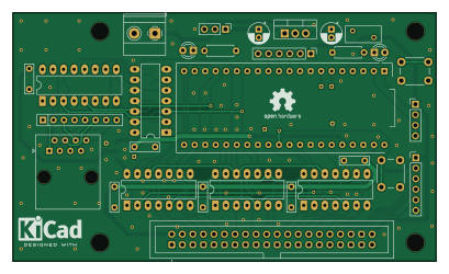
About the Smart Reciver Max Exp Pico PCB
Smart Reciver Max Exp Pico is an open source RP2040/RP2350 PCB design by computergeek1507, published on GitHub under the CERN-OHL-S-2.0 license. It is a 2-layer board measuring 102 × 60 mm, with 30 components from 24 distinct parts.
Its main chip is the UNIVERSE5V, from the RP2040/RP2350 family. Other key parts include the POCKETBEAGLE-SC-569, SN74HCT245N, UA9638CP, 24L256 and 74LS125. By type, the board carries 8 capacitors, 7 ICs, 7 connectors, 3 resistors, 2 switches and 2 diodes.
It belongs with the wearables and displays & leds designs in this gallery.
From the project
Open source FPP PB16 Pixel Controller
This documentation describes Open Hardware and is licensed under the CERN Open Hardware License Version 2 - Strongly Reciprocal. (CERN-OHL-S)
You may redistribute and modify this documentation under the terms of the CERN OHL-S-v2 (https://ohwr.org/cernohls_v2.txt). This documentation is distributed WITHOUT ANY EXPRESS OR IMPLIED WARRANTY, INCLUDING OF MERCHANTABILITY, SATISFACTORY QUALITY AND FITNESS FOR A PARTICULAR PURPOSE. Please see the CERN OHL v2-S for applicable conditions
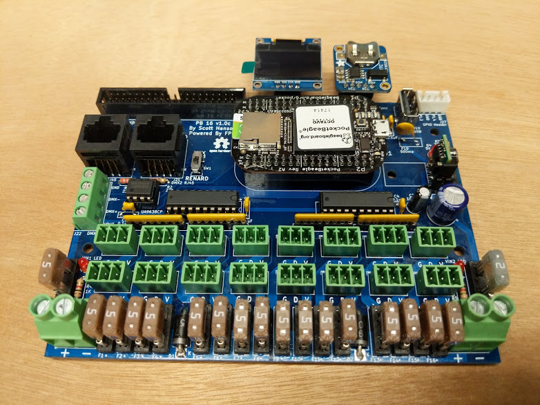
Main components on the Smart Reciver Max Exp Pico
Smart Reciver Max Exp Pico bill of materials (BOM)
30 components, 24 distinct parts — part numbers from the project's BOM.
| Qty | Part | Footprint | Refs |
|---|---|---|---|
| 1 | POCKETBEAGLE-SC-569 L7805 | TO-220-3_Vertical | U1 |
| 1 | UNIVERSE5V raspberrypi-pico-module | raspberrypi-pico-module-nohole | U2 |
| 2 | SN74HCT245N 74LS125 | DIP-14_W7.62mm_LongPads | U3, U4 |
| 1 | UA9638CP 74LS125 | DIP-14_W7.62mm_LongPads | U5 |
| 1 | 24L256 AM26C32IN | DIP-16_W7.62mm_LongPads | U6 |
| 1 | 74LS125 | DIP-14_W7.62mm_LongPads | U7 |
| 1 | STRING1 Power In | TerminalBlock_Phoenix_MKDS-1,5-2_1x02_P5.00mm_Horizontal | J1 |
| 1 | STRING2 Expansion Header | IDC-Header_2x20_P2.54mm_Vertical | J2 |
| 1 | STRING3 RJ45 | RJ45_Amphenol_54602-x08_Horizontal | J3 |
| 1 | STRING4 VIN_Voltage | PinHeader_1x03_P2.54mm_Vertical | J4 |
| 1 | STRING5 EXT1 | PinHeader_1x04_P2.54mm_Vertical | J5 |
| 1 | STRING6 EXT2 | PinHeader_1x06_P2.54mm_Vertical | J6 |
| 1 | STRING7 EXT3 | PinHeader_1x06_P2.54mm_Vertical | J7 |
| 1 | 3544-2 Fuse | Fuse_BelFuse_0ZRE0005FF_L8.3mm_W3.8mm | F1 |
| 1 | USR | SW_PUSH_6mm | SW1 |
| 1 | RUN | SW_PUSH_6mm | SW2 |
| 1 | SB5100-T VIN LED | LED_D3.0mm_Clear | D1 |
| 1 | SB5100-T Stat LED | LED_D3.0mm_Clear | D2 |
| 1 | 220UF 100uF | CP_Radial_D5.0mm_P2.00mm | C1 |
| 1 | 100UF 10uF | CP_Radial_D5.0mm_P2.00mm | C2 |
Show 4 more
| Qty | Part | Footprint | Refs |
|---|---|---|---|
| 6 | 0.1UF 0.1uF | C_Rect_L7.0mm_W2.0mm_P5.00mm | C3, C4, C5, C6, C7, C8 |
| 1 | 120 1K | R_Axial_DIN0207_L6.3mm_D2.5mm_P7.62mm_Horizontal | R1 |
| 1 | 120 | R_Axial_DIN0207_L6.3mm_D2.5mm_P7.62mm_Horizontal | R2 |
| 1 | 120 | R_Array_SIP8 | RN1 |
Smart Reciver Max Exp Pico design files
The KiCad project lives in the computergeek1507/PB_16 repository on GitHub; these links point at the commit this page was built from.
Smart Reciver Max Exp Pico: common questions
What microcontroller does the Smart Reciver Max Exp Pico use?
The Smart Reciver Max Exp Pico is built around the UNIVERSE5V, from the RP2040/RP2350 family.
How big is the Smart Reciver Max Exp Pico PCB?
The Smart Reciver Max Exp Pico measures 102 × 60 mm, has 2 copper layers and is 1.6 mm thick.
How many components are on the Smart Reciver Max Exp Pico?
30 components, from 24 distinct parts, with part numbers taken from the project's own BOM. The full bill of materials is listed on this page.
Where can I download the Smart Reciver Max Exp Pico design files?
From the computergeek1507/PB_16 repository on GitHub, which has the KiCad layout and the BOM; the links under Design files point to each one.
Can I use the Smart Reciver Max Exp Pico design in my own project?
Yes, under the terms of its CERN-OHL-S-2.0 license, which computergeek1507 chose for the repository.
Can I test firmware for the Smart Reciver Max Exp Pico without the hardware?
Yes. HardLabs builds a simulation of the board from its netlist and BOM, so you can run and debug RP2040/RP2350 firmware against it before you order a PCB.
More boards in PB_16
 Raspberry Pi
Pi CM4 16
142.1 × 106 mm113 parts2LCERN-OHL-S-2.078
Pi Zero W 16
142.1 × 93 mm92 parts2LCERN-OHL-S-2.078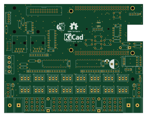
BBB 16
148.8 × 116.9 mm92 parts2LCERN-OHL-S-2.078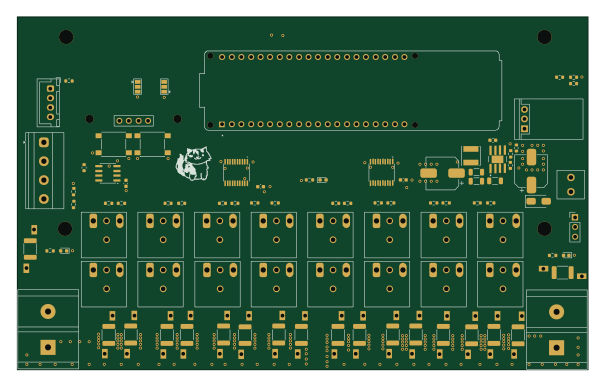 ESP32
ESP32ESP32P4 16
151.1 × 93.4 mm91 parts2LCERN-OHL-S-2.078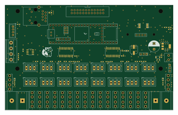 NXP
NXPTeensy 16
148.8 × 92.6 mm88 parts2LCERN-OHL-S-2.078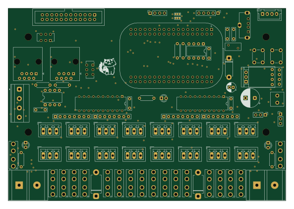
PB 16
148.1 × 102.6 mm83 parts2LCERN-OHL-S-2.078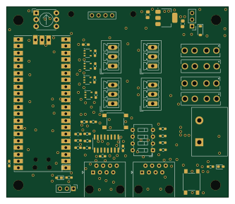 RP2040/RP2350
SM Receiver
83.2 × 71.4 mm53 parts2LCERN-OHL-S-2.078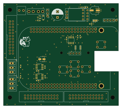
BBB16 Expansion
99.5 × 88.5 mm40 parts2LCERN-OHL-S-2.078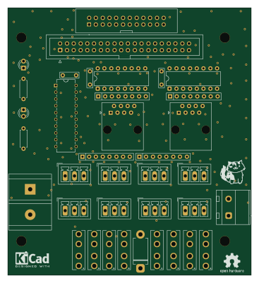
Multi Expansion
91.1 × 100 mm37 parts2LCERN-OHL-S-2.078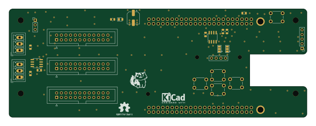
BBB16 Flex
162.6 × 59.2 mm26 parts2LCERN-OHL-S-2.078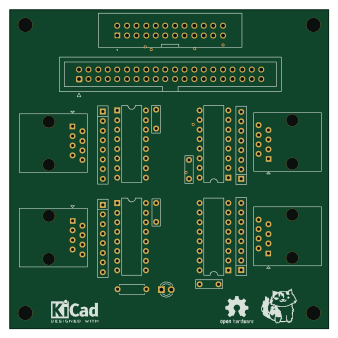
Diff Expansion
84.3 × 84.3 mm20 parts2LCERN-OHL-S-2.078
Similar boards
 RP2040/RP2350
Open Book Abridged Edition
joeycastillo
85 × 115 mm29 parts2LCC-BY-SA-4.08.1k RP2040/RP2350
Corne
foostan
277.2 × 107.5 mm164 parts2LCC-BY-4.07.7k RP2040/RP2350
Corne
277.2 × 107.5 mm164 parts2LCC-BY-4.07.7k RP2040/RP2350
LogicAnalyzer
gusmanb
57 × 55.2 mm6 parts2LGPL-3.05.0k RP2040/RP2350
Jitx design
55.5 × 65 mm26 parts4LGPL-3.05.0k RP2040/RP2350
Pro V2
kata0510
290.1 × 130 mm270 parts2LMIT2.3k