
ADSR CONTROLLER

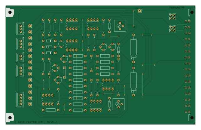
About the ADSR CONTROLLER PCB
ADSR CONTROLLER is an open source PCB design by Desval27, published on GitHub under the MIT license. It is a 2-layer board measuring 160 × 100 mm, with 77 components from 40 distinct parts.
Other key parts include the OpAmp. By type, the board carries 30 resistors, 22 connectors, 6 ICs, 6 diodes, 5 transformers and 4 capacitors.
It belongs with the audio designs in this gallery.
From the project
Knock-off of the Elektor Formant Synthesizer project with the initial goal of being quasi-authentic and secondary goal undecided. Probably tweaks of some kind.
The ADSR Controller expands the capabilities of the standard Formant ADSR module by adding clock-driven repeat and delayed triggering functions. An external square-wave clock source (typically an LFO or VC-LFO) can repeatedly retrigger the envelope, enabling rhythmic modulation and gated effects. Repeat operation may be disabled, run continuously (Auto), or only while an external or keyboard gate is active. An adjustable delay function can also postpone envelope triggering, making the module useful for creating delayed attacks, repeating envelopes, and more complex modulation patterns.
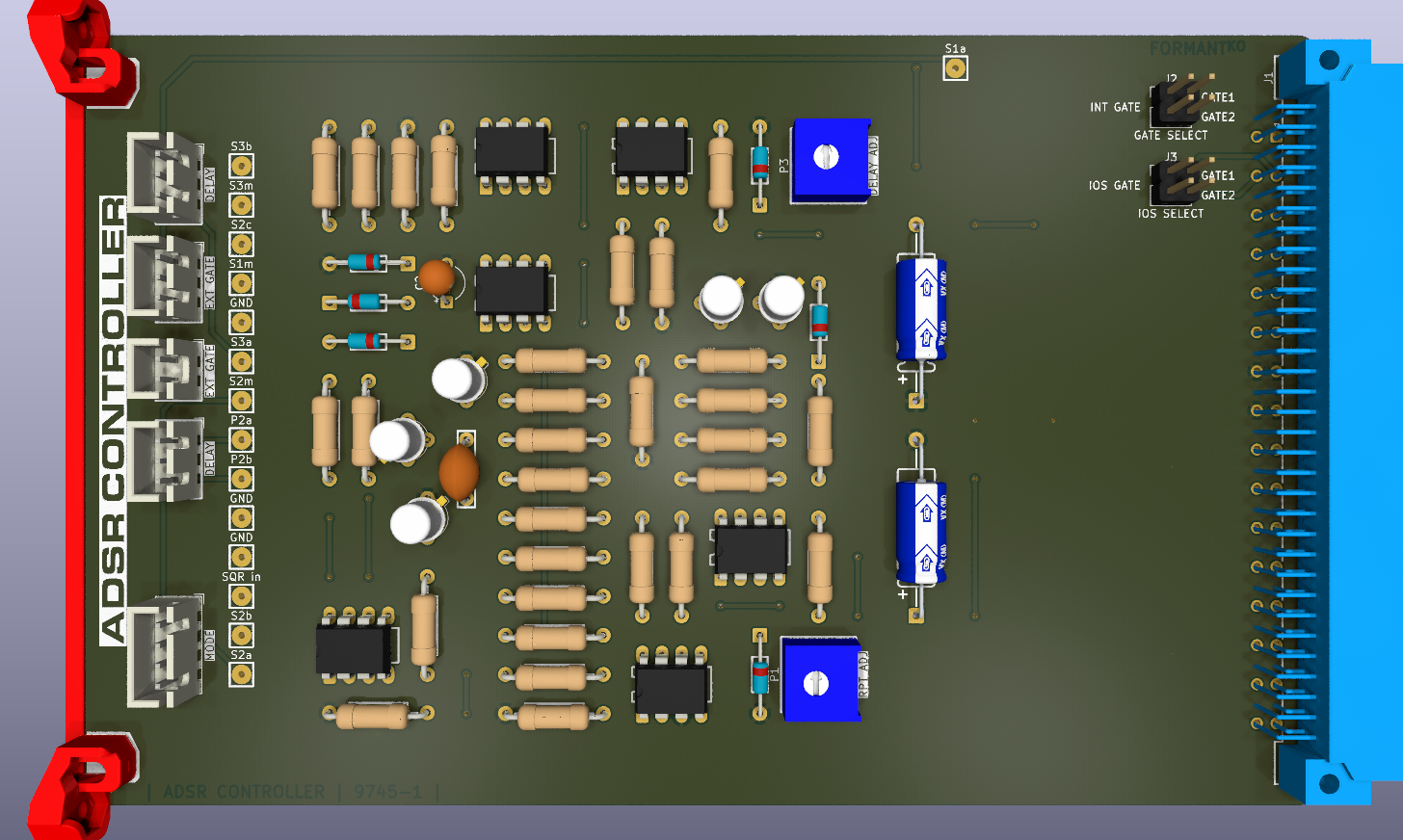
Main components on the ADSR CONTROLLER
ADSR CONTROLLER bill of materials (BOM)
77 components, 40 distinct parts — part numbers from the project's BOM.
| Qty | Part | Footprint | Refs |
|---|---|---|---|
| 6 | OpAmp | DIP-8 | IC1, IC2, IC3, IC4, IC5, IC6 |
| 1 | CardConnector | CardConnector | J1 |
| 1 | GATE SELECT | PinHeader_2x02_P2.54mm_Vertical | J2 |
| 1 | IOS SELECT | PinHeader_2x02_P2.54mm_Vertical | J3 |
| 1 | MonoJack | PanelConnector_1x02 | J4 |
| 1 | S1A S1a | Wire_1x01_General | J5 |
| 1 | S2A S2a | Wire_1x01_General | J6 |
| 1 | S2B S2b | Wire_1x01_General | J7 |
| 1 | SQR in | Wire_1x01_General | J8 |
| 3 | GND | Wire_1x01_General | J9, J10, J15 |
| 1 | P2A P2a | Wire_1x01_General | J11 |
| 1 | P2B P2b | Wire_1x01_General | J12 |
| 1 | S2M S2m | Wire_1x01_General | J13 |
| 1 | S3A S3a | Wire_1x01_General | J14 |
| 1 | S1M S1m | Wire_1x01_General | J16 |
| 1 | S2C S2c | Wire_1x01_General | J17 |
| 1 | S3M S3m | Wire_1x01_General | J18 |
| 1 | S3B S3b | Wire_1x01_General | J19 |
| 1 | 1k | Potentiometer_Trimmer_PinSwap | P1 |
| 1 | 1M | PanelConnector_1x03 | P2 |
Show 20 more
| Qty | Part | Footprint | Refs |
|---|---|---|---|
| 1 | 1k | Potentiometer_Trimmer | P3 |
| 1 | CardBracket | CardBracket | MH1 |
| 2 | SW | PanelConnector_1x03 | S1, S3 |
| 1 | MODE | PanelConnector_1x04 | S2 |
| 5 | BC109C | TO-18_Wide | T1, T2, T3, T4, T5 |
| 4 | DUS | DUS | D1, D2, D3, D6 |
| 2 | DUG | DUG | D4, D5 |
| 1 | 10N 10n | C_Rect_300 | C1 |
| 1 | 2µ2 | CP_Radial_Tantal_D4.5mm_P5.00mm | C2 |
| 2 | 10µ | CP_Axial_900 | C3, C4 |
| 11 | 100K 100k | R_Axial_Horizontal | R1, R2, R4, R8, R9, R10, R13, R14 +3 |
| 3 | 4K7 4k7 | R_Axial_Horizontal | R3, R7, R18 |
| 3 | 10K 10k | R_Axial_Horizontal | R5, R17, R23 |
| 2 | 27K 27k | R_Axial_Horizontal | R6, R24 |
| 4 | 33K 33k | R_Axial_Horizontal | R11, R16, R22, R30 |
| 2 | 5K6 5k6 | R_Axial_Horizontal | R12, R15 |
| 1 | 1k | R_Axial_Horizontal | R19 |
| 1 | 220R | R_Axial_Horizontal | R20 |
| 2 | 6K8 6k8 | R_Axial_Horizontal | R25, R28 |
| 1 | 330R | R_Axial_Horizontal | R29 |
ADSR CONTROLLER design files
The KiCad project lives in the Desval27/FormantKO repository on GitHub; these links point at the commit this page was built from.
ADSR CONTROLLER: common questions
How big is the ADSR CONTROLLER PCB?
The ADSR CONTROLLER measures 160 × 100 mm, has 2 copper layers and is 1.6 mm thick.
How many components are on the ADSR CONTROLLER?
77 components, from 40 distinct parts, with part numbers taken from the project's own BOM. The full bill of materials is listed on this page.
Where can I download the ADSR CONTROLLER design files?
From the Desval27/FormantKO repository on GitHub, which has the KiCad layout, the schematic and the BOM; the links under Design files point to each one.
Can I use the ADSR CONTROLLER design in my own project?
Yes, under the terms of its MIT license, which Desval27 chose for the repository.
More boards in FormantKO
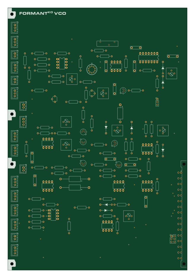
VCO
160 × 233.4 mm129 parts2LMIT0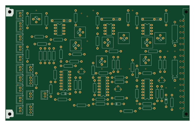
LFOs
160 × 100 mm94 parts2LMIT0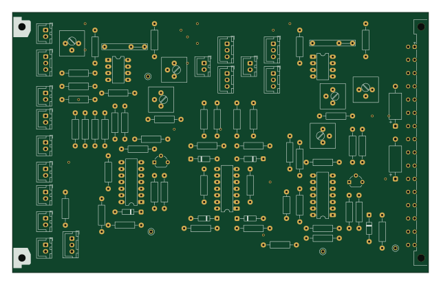
VC-LFOs
160 × 100 mm92 parts2LMIT0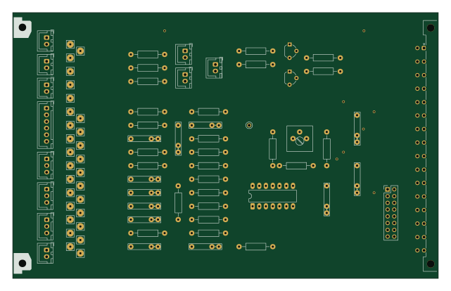
COM
160 × 100 mm85 parts2LMIT0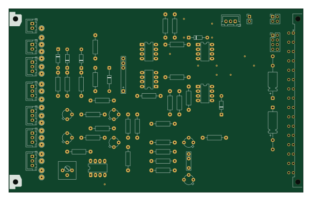
ADSR
160 × 100 mm82 parts2LMIT0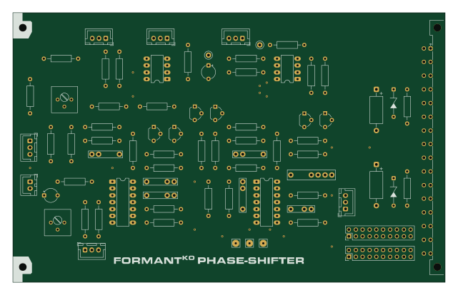
PHASE-SHIFTER
160 × 100 mm79 parts2LMIT0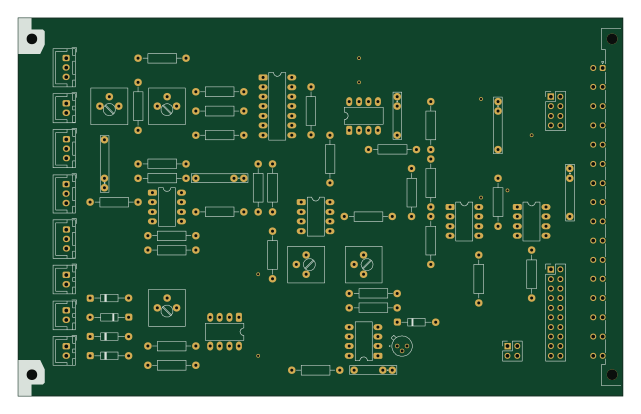
DUAL VCA
160 × 100 mm68 parts2LMIT0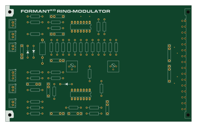
RING MODULATOR
160 × 100 mm60 parts2LMIT0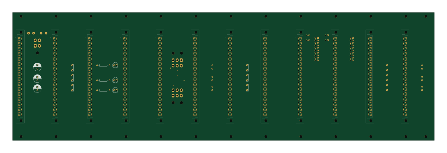
BACKPLANE A
428.6 × 130.2 mm49 parts2LMIT0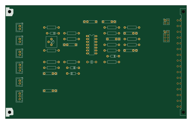
ENVELOPE FOLLOWER
160 × 100 mm40 parts2LMIT0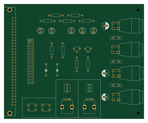
MODULE TESTER
127 × 104.1 mm36 parts2LMIT0
Similar boards
OtterCastAudioV2
Ottercast
50 × 49.3 mm216 parts4LMIT665
FunBox
GuitarML
59.7 × 67.5 mm63 parts2LMIT278
Eurorack pmod
apfaudio
35 × 110 mm116 parts4LCERN-OHL-S-2.0239
XassetteAsterisk
SdtElectronics
56 × 56 mm137 parts2LCERN-OHL-W-2.0229
AddOnC
freeDSP
380 × 45 mm97 parts2LCC-BY-SA-4.0222
AddOnA
178 × 39 mm55 parts2LCC-BY-SA-4.0222