
FOXSI-4 Formatter/Plenum board

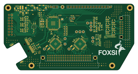
About the FOXSI-4 Formatter/Plenum board
FOXSI-4 Formatter/Plenum board is an open source PIC PCB design by foxsi, published on GitHub. It is a 4-layer board measuring 116.8 × 59.7 mm, with 133 components from 48 distinct parts.
Its main chip is the PIC18F66J60-IPT, from the PIC family. Other key parts include the 74LVC1G86, 74LVC1G02, 74LVC1G08, NBA3N011S and SN74LVC1T45DBV. By type, the board carries 55 capacitors, 29 resistors, 20 ICs, 14 test points, 7 connectors and 3 inductors.
From the project
Circuit boards designed in Minnesota for FOXSI-4
Main components on the FOXSI-4 Formatter/Plenum board
FOXSI-4 Formatter/Plenum board bill of materials (BOM)
133 components, 48 distinct parts — part numbers from the project's BOM.
| Qty | Part | Footprint | Refs |
|---|---|---|---|
| 1 | PIC18F66J60-IPT | TQFP-64_10x10mm_P0.5mm | U1 |
| 1 | 74LVC1G86 | SOT-23-5 | U2 |
| 2 | 74LVC1G02 | SOT-23-5 | U3, U4 |
| 1 | 74LVC1G08 | SOT-23-5 | U5 |
| 6 | NBA3N011S | SOT-23-5 | U6, U7, U8, U9, U10, U11 |
| 3 | SN74LVC1T45DBV | SOT-23-6 | U12, U13, U14 |
| 1 | BME680 | Bosch_LGA-8_3x3mm_P0.8mm_ClockwisePinNumbering | U15 |
| 1 | TPS62082 | WSON-8-1EP_2x2mm_P0.5mm_EP0.9x1.6mm | U16 |
| 1 | TXB0108DQSR | USON-20_2x4mm_P0.4mm | U17 |
| 2 | LTC2983 | LQFP-48_7x7mm_P0.5mm | U18, U19 |
| 1 | BMI270 | BMI270 | U20 |
| 1 | 25 MHz | Crystal_SMD_3225-4Pin_3.2x2.5mm | Y1 |
| 1 | Conn_02x01 | PinHeader_1x02_P2.54mm_Vertical | J1 |
| 1 | Conn_02x08_Odd_Even | PinHeader_2x08_P2.54mm_Vertical | J2 |
| 1 | Conn_03x20_MountingPin | Harwin_JTek-Male_3x20_P2.00mm_Horizontal | J3 |
| 1 | Conn_02x06_Row_Letter_First | Harwin_JTek-Male_2x6_P2.00mm_Horizontal | J4 |
| 1 | RJ45_Wuerth_7498210220A | RJ45_Wuerth_7498210220A_Horizontal | J5 |
| 1 | Conn_01x16 | PinHeader_1x16_P2.54mm_Vertical | J7 |
| 1 | Conn_01x03 | PinSocket_1x03_P2.54mm_Vertical | J9 |
| 2 | ? 1% | R_1210_3225Metric | RSENSE1, RSENSE2 |
Show 28 more
| Qty | Part | Footprint | Refs |
|---|---|---|---|
| 2 | SW_Push_LED_Wuerth_WS-TASL | SW_Tactile_SPST_Wuerth_WS-TASL | SW1, SW2 |
| 1 | TestPoint | TestPoint_Loop_D2.60mm_Drill1.4mm_Beaded | TP1 |
| 13 | TestPoint | TestPoint_THTPad_D2.0mm_Drill1.0mm | TP2, TP4, TP5, TP6, TP7, TP8, TP9, TP10 +5 |
| 2 | 120Ω | R_0603_1608Metric | L1, L3 |
| 1 | 1 µH | L_Wuerth_MAPI-3020 | L2 |
| 32 | 0.1µF | C_0603_1608Metric | C1, C5, C6, C7, C8, C9, C10, C11 +24 |
| 2 | 10pF 1% | C_0603_1608Metric | C2, C3 |
| 1 | 10µF | C_0603_1608Metric | C4 |
| 1 | 10µF | C_1206_3216Metric | C15 |
| 1 | 22µF | C_1206_3216Metric | C19 |
| 2 | 10 µF (X7R) | C_0603_1608Metric | C26, C27 |
| 2 | 10 µF (X5R) | C_0603_1608Metric | C28, C29 |
| 2 | 10 µF | C_0603_1608Metric | C30, C31 |
| 2 | 1 µF | C_0603_1608Metric | C32, C33 |
| 4 | 0.1 µF | C_0603_1608Metric | C34, C35, C36, C37 |
| 3 | 0.1µF | C_1206_3216Metric | C49, C50, C51 |
| 2 | 56pF 5% | C_0603_1608Metric | C52, C53 |
| 1 | 10µF, 16V | C_0603_1608Metric | C54 |
| 1 | 10kΩ | R_0603_1608Metric | R1 |
| 1 | 470Ω | R_0603_1608Metric | R2 |
| 1 | 150Ω | R_0603_1608Metric | R3 |
| 1 | 2.26kΩ 1% | R_0603_1608Metric | R4 |
| 15 | 4.7kΩ | R_0603_1608Metric | R5, R14, R15, R18, R19, R20, R21, R22 +7 |
| 2 | 180Ω | R_0603_1608Metric | R6, R10 |
| 1 | 200Ω | R_0603_1608Metric | R7 |
| 4 | 49.9Ω 1% | R_0603_1608Metric | R8, R9, R12, R13 |
| 1 | 47Ω | R_1210_3225Metric | R11 |
| 2 | 75Ω | R_0603_1608Metric | R16, R17 |
FOXSI-4 Formatter/Plenum board design files
The KiCad project lives in the foxsi/UMN-boards-FOXSI-4 repository on GitHub; these links point at the commit this page was built from.
FOXSI-4 Formatter/Plenum board: common questions
What microcontroller does the FOXSI-4 Formatter/Plenum board use?
The FOXSI-4 Formatter/Plenum board is built around the PIC18F66J60-IPT, from the PIC family.
How big is the FOXSI-4 Formatter/Plenum board?
The FOXSI-4 Formatter/Plenum board measures 116.8 × 59.7 mm, has 4 copper layers and is 1.561592 mm thick.
How many components are on the FOXSI-4 Formatter/Plenum board?
133 components, from 48 distinct parts, with part numbers taken from the project's own BOM. The full bill of materials is listed on this page.
Where can I download the FOXSI-4 Formatter/Plenum board design files?
From the foxsi/UMN-boards-FOXSI-4 repository on GitHub, which has the KiCad layout, the schematic and the BOM; the links under Design files point to each one.
Can I use the FOXSI-4 Formatter/Plenum board design in my own project?
The repository has no license, so all rights stay with foxsi. Use it as a reference, and ask the author before reusing the design.
Can I test firmware for the FOXSI-4 Formatter/Plenum board without the hardware?
Yes. HardLabs builds a simulation of the board from its netlist and BOM, so you can run and debug PIC firmware against it before you order a PCB.
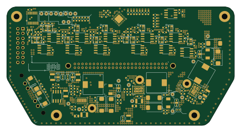
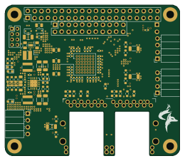
More boards in UMN-boards-FOXSI-4
Similar boards
 PIC
PICPslab hardware
fossasia
99 × 53.3 mm187 parts4LApache-2.01.7k PIC
PICGB-MBCTEST
Gekkio
51.4 × 61 mm32 parts2LCC-BY-4.0376 PIC
PICGB-CARTPP-DIY
100 × 100 mm22 parts2LCC-BY-4.0376 PIC
PICGB-LIVE32
51.4 × 61 mm46 parts4LCC-BY-4.0376 PIC
PICGB-BENCH-G1
100 × 100 mm98 parts4LCC-BY-4.0376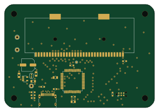 PIC
PICGB-CARTPP-XC
80 × 55 mm19 parts2LCC-BY-4.0376