
Microbot v1.1

About the Microbot v1.1 PCB
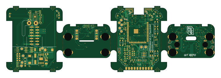
Microbot v1.1 is an open source ESP32 PCB design by Freimor, published on GitHub. It is a 4-layer board measuring 185 × 58.6 mm, with 190 components from 87 distinct parts.
Its main chip is the ESP32-S3-WROOM-1, from the ESP32 family. Other key parts include the IP4234CZ6, ST1S12XX, XC6219B152MR, XC6219B282MR and LC709203FQH-01TWG. By type, the board carries 66 capacitors, 50 resistors, 18 ICs, 16 diodes, 9 LEDs and 7 transistors.
Main components on the Microbot v1.1
Microbot v1.1 bill of materials (BOM)
190 components, 87 distinct parts.
| Qty | Part | Footprint | Refs |
|---|---|---|---|
| 1 | IP4234CZ6 | SC-74-6_1.55x2.9mm_P0.95mm | U1 |
| 1 | ESP32-S3-WROOM-1 | ESP32-S3-WROOM-1 | U2 |
| 1 | ST1S12XX | TSOT-23-5 | U3 |
| 1 | XC6219B152MR | SOT-23-5 | U4 |
| 1 | XC6219B282MR | SOT-23-5 | U5 |
| 1 | LC709203FQH-01TWG | WDFN-8-1EP_4x3mm_P0.65mm_EP2.4x1.8mm | U6 |
| 1 | ADS1015IDGS | TSSOP-10_3x3mm_P0.5mm | U7 |
| 1 | 74LVC2G17 | SOT-23-6_Handsoldering | U8 |
| 1 | 74LVC1G80 | 74LVC1G80 | U9 |
| 1 | BQ51050BRHL | Texas_VQFN-RHL-20 | U10 |
| 1 | TP5410 | TP5410 | U11 |
| 4 | OH137 | TO-92S | U12, U14, U15, U16 |
| 1 | DRV8834 | HTSSOP-24-1EP_4.4x7.8mm_P0.65mm_EP3.4x7.8mm_Mask2.4x2.98mm | U13 |
| 1 | LTR-308ALS-01 | LightSensor_LTR-303ALS-01 | U17 |
| 1 | VL53L0CXV0DH1 | ToF_LaserRange_VL53L0X_StandartFootprint | U18 |
| 4 | LineSensor_GP2S700HCP | GP2S700HCP | A1, A2, A3, A4 |
| 2 | Motor_DC | GW12-N20 with encoders PCB footprint | M1, M2 |
| 1 | SI2302 | SOT-23 | Q1 |
| 1 | Q_Dual_PMOS_IRF9362 | SOP-8_3.76x4.96mm_P1.27mm | Q2 |
| 4 | BSS138 (or AO3400) | SOT-23 | Q3, Q4, Q5, Q6 |
Show 67 more
| Qty | Part | Footprint | Refs |
|---|---|---|---|
| 1 | SS8050 | SOT-23 | Q7 |
| 1 | DSX321G 24 MHZ | Crystal_SMD_3225-4Pin_3.2x2.5mm_HandSoldering | Y1 |
| 1 | USB_C_Receptacle_USB2.0 | RUICHI_TYPE-C-16PF-020 | J1 |
| 2 | TOP2BOTTOM | PinHeader_2x07_P2.54mm_Vertical_SMD | J2, J6 |
| 1 | Jumper | PinHeader_1x02_P2.54mm_Vertical | J5 |
| 1 | Battery | Conn_Molex_2026560021(Pico-EZmate_Slim) | BT1 |
| 1 | Buzzer | PASSIVE_SMD_MLT-8530 | BZ1 |
| 1 | OV5640 | CAM_OV5640_OMRON_XF2M-2415-1A | CAM1 |
| 1 | BuzzerON | SolderJumper-2_P1.3mm_Open_RoundedPad1.0x1.5mm | JP1 |
| 1 | P_F_CONN | SolderJumper-2_P1.3mm_Open_RoundedPad1.0x1.5mm | JP4 |
| 1 | 16uH 191mOhm | COIL | L_Receiver1 |
| 1 | FLASH | SW_SMD_KLS7-TS3401 | SW1 |
| 1 | EN | SW_SMD_KLS7-TS3401 | SW2 |
| 1 | START | SW_SMD_KLS7-TS3401 | SW3 |
| 1 | PWRON | SW_SMD_KLS7-TS3401 | SW4 |
| 8 | SK6812_SIDE | ADR_LED_SK6812_SIDE | LED1, LED2, LED3, LED4, LED5, LED6, LED7, LED8 |
| 1 | SK6812MINI | LED_SK6812MINI_PLCC4_3.5x3.5mm_P1.75mm | LED9 |
| 1 | 1N5819W | D_SOD-123 | D1 |
| 1 | SS34 | D_SMA_Handsoldering | D2 |
| 1 | RED | LED_SIDE_KA-2810_Kingbright | D3 |
| 1 | SMF6V0A | D_SOD-123F | D4 |
| 1 | SS32 | D_SMA-SMB_Universal_Handsoldering | D5 |
| 1 | CHRG | LED_SIDE_KA-2810_Kingbright | D6 |
| 1 | STDBY | LED_SIDE_KA-2810_Kingbright | D7 |
| 4 | D_Photo | Photoresistor_TH_Vertical | D8, D9, D15, D16 |
| 4 | HL-A-2835H358W-2-S1-08L-HR3 | LED_Everlight-SMD3528_3.5x2.8mm_67-21ST | D10, D11, D12, D13 |
| 1 | 1N4007 | D_SOD-123F | D14 |
| 1 | ILHB0805ER121V | L_0805_2012Metric_Pad1.15x1.40mm_HandSolder | FB1 |
| 1 | VLS201610CX-2R2M-1 | IND_VLS201610CX-220M-1 | L1 |
| 1 | SPM5020T-100M-LR 10uH | INDUCTOR_SPM5020T | L2 |
| 1 | 4u7 | C_0603_1608Metric_Pad1.08x0.95mm_HandSolder | C1 |
| 2 | 2u2 | C_0603_1608Metric_Pad1.08x0.95mm_HandSolder | C2, C3 |
| 4 | 10uF | C_0603_1608Metric | C4, C21, C39, C41 |
| 20 | 100n | C_0402_1005Metric_Pad0.74x0.62mm_HandSolder | C5, C6, C7, C16, C17, C18, C19, C20 +12 |
| 3 | 1uF | C_0603_1608Metric_Pad1.08x0.95mm_HandSolder | C8, C15, C30 |
| 1 | 4.7uF | C_0603_1608Metric_Pad1.08x0.95mm_HandSolder | C9 |
| 7 | 10uF | C_0603_1608Metric_Pad1.08x0.95mm_HandSolder | C10, C11, C12, C13, C14, C50, C52 |
| 1 | 68n | C_0402_1005Metric_Pad0.74x0.62mm_HandSolder | C27 |
| 1 | 47n | C_0402_1005Metric_Pad0.74x0.62mm_HandSolder | C28 |
| 1 | 39n | C_0402_1005Metric_Pad0.74x0.62mm_HandSolder | C29 |
| 1 | 2n2 25v | C_0402_1005Metric_Pad0.74x0.62mm_HandSolder | C31 |
| 1 | 100p 25v | C_0402_1005Metric_Pad0.74x0.62mm_HandSolder | C32 |
| 2 | 470n 25v | C_0402_1005Metric_Pad0.74x0.62mm_HandSolder | C33, C38 |
| 2 | 47n 25v | C_0402_1005Metric_Pad0.74x0.62mm_HandSolder | C34, C37 |
| 2 | 10nF 10v | C_0402_1005Metric_Pad0.74x0.62mm_HandSolder | C35, C36 |
| 1 | 1uF | C_0603_1608Metric | C40 |
| 4 | 100nF | C_0402_1005Metric_Pad0.74x0.62mm_HandSolder | C42, C43, C51, C68 |
| 2 | 47uF Tantal | CP_EIA-7343-31_Kemet-D | C44, C47 |
| 2 | 22uF | C_0805_2012Metric_Pad1.18x1.45mm_HandSolder | C45, C48 |
| 4 | 20pF | C_0603_1608Metric_Pad1.08x0.95mm_HandSolder | C53, C56, C57, C58 |
| 1 | 10nF | C_0402_1005Metric_Pad0.74x0.62mm_HandSolder | C54 |
| 1 | 2.2uF | C_0603_1608Metric_Pad1.08x0.95mm_HandSolder | C55 |
| 2 | 4.7uF | C_0603_1608Metric | C59, C62 |
| 2 | 1M | R_0402_1005Metric_Pad0.72x0.64mm_HandSolder | R1, R12 |
| 4 | 5.1k | R_0402_1005Metric_Pad0.72x0.64mm_HandSolder | R2, R3, R7, R8 |
| 2 | 4.7k | R_0402_1005Metric_Pad0.72x0.64mm_HandSolder | R4, R5 |
| 22 | 10k | R_0402_1005Metric_Pad0.72x0.64mm_HandSolder | R6, R9, R10, R13, R14, R18, R21, R23 +14 |
| 1 | 220k | R_0402_1005Metric_Pad0.72x0.64mm_HandSolder | R11 |
| 4 | 100 | R_0805_2012Metric_Pad1.20x1.40mm_HandSolder | R15, R22, R24, R29 |
| 5 | 820 | R_0402_1005Metric_Pad0.72x0.64mm_HandSolder | R16, R33, R37, R38, R39 |
| 2 | 200 | R_0402_1005Metric_Pad0.72x0.64mm_HandSolder | R17, R19 |
| 1 | 398 | R_0402_1005Metric_Pad0.72x0.64mm_HandSolder | R20 |
| 1 | 0.3 | R_1210_3225Metric_Pad1.30x2.65mm_HandSolder | R25 |
| 2 | 1.3k | R_0402_1005Metric_Pad0.72x0.64mm_HandSolder | R27, R28 |
| 2 | 1 | R_1206_3216Metric_Pad1.30x1.75mm_HandSolder | R34, R35 |
| 1 | 1k | R_0402_1005Metric_Pad0.72x0.64mm_HandSolder | R46 |
| 1 | 10k (or DNP) | R_0402_1005Metric_Pad0.72x0.64mm_HandSolder | R47 |
Microbot v1.1 design files
The KiCad project lives in the Freimor/HRDW-Microbot repository on GitHub; these links point at the commit this page was built from.
- LayoutKiCAD/Microbot_v1.1.kicad_pcb
- SchematicKiCAD/Microbot_v1.1.kicad_sch
Microbot v1.1: common questions
What microcontroller does the Microbot v1.1 use?
The Microbot v1.1 is built around the ESP32-S3-WROOM-1, from the ESP32 family.
How big is the Microbot v1.1 PCB?
The Microbot v1.1 measures 185 × 58.6 mm, has 4 copper layers and is 2 mm thick.
How many components are on the Microbot v1.1?
190 components, from 87 distinct parts. The full bill of materials is listed on this page.
Where can I download the Microbot v1.1 design files?
From the Freimor/HRDW-Microbot repository on GitHub, which has the KiCad layout and the schematic; the links under Design files point to each one.
Can I use the Microbot v1.1 design in my own project?
The repository has no license, so all rights stay with Freimor. Use it as a reference, and ask the author before reusing the design.
Can I test firmware for the Microbot v1.1 without the hardware?
Yes. HardLabs builds a simulation of the board from its netlist and BOM, so you can run and debug ESP32 firmware against it before you order a PCB.
More boards in HRDW-Microbot
Similar boards
 ESP32
ESP32Open Book Abridged Edition
joeycastillo
85 × 115 mm65 parts2LCC-BY-SA-4.08.1k ESP32
ESP32Badge
atopile
56.3 × 39 mm239 parts4LMIT4.0k ESP32
ESP32Esp32 minimal
36.2 × 26.8 mm20 parts2LMIT4.0k ESP32
ESP32Racer
StuckAtPrototype
36 × 50.2 mm70 parts4LApache-2.03.8k ESP32
ESP32Controller
29 × 74 mm58 parts4LApache-2.03.8k ESP32
ESP32Bitaxe
skot
56.5 × 99.8 mm86 parts4LCERN-OHL-S-2.01.4k