
Led button

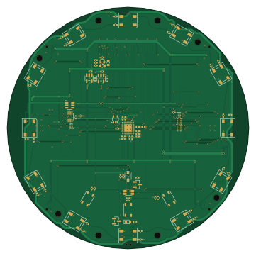
About the Led button PCB
Led button is an open source ESP32 PCB design by GeniePod, published on GitHub under the CERN-OHL-S-2.0 license. It is a 2-layer board measuring 90 × 90 mm, with 116 components from 32 distinct parts.
Its main chip is the ESP32-H2-MINI-1-N4, from the ESP32 family. Other key parts include the SN74LVC1T45DBV, 74LVC3G14, SN74LVC1G74DCUR, ES7210 and 74LVC1G08. By type, the board carries 50 capacitors, 26 resistors, 15 ICs, 12 LEDs, 4 microphones and 4 switches.
From the project
GeniePod Home V1 hardware: MVP testing build, wiring, BOM, and planned interface-board/enclosure docs.
GeniePod Home V1 board layouts, derived from the schematics in ../schematic/.
empty — nothing here yet. The schematics arrive first; the layout follows once the Home V1 interface-board schematic stabilizes.
- Tool: KiCad 8.x. Gerbers + drill + position file committed alongside .kicadpcb so the board is manufacturable without a KiCad install. PNG renders make GitHub previews useful. - Layer stack: 4-layer for any board carrying I2S clocks at 24-48 kHz with ESD protection on USB. 2-layer is fine for the simplest passthrough. - DFM target: JLCPCB defaults unless a board specifically needs…
Main components on the Led button
Led button bill of materials (BOM)
116 components, 32 distinct parts.
| Qty | Part | Footprint | Refs |
|---|---|---|---|
| 1 | SN74LVC1T45DBV | SOT-23-6 | U1 |
| 1 | 74LVC3G14 | VSSOP-8_2.3x2mm_P0.5mm | U2 |
| 1 | SN74LVC1G74DCUR Texas Instruments | VSSOP-8_2.3x2mm_P0.5mm | U3 |
| 1 | ES7210 Everest-semi(Everest Semiconductor) | VQFN-32-1EP_4x4mm_P0.4mm_EP2.8x2.8mm | U4 |
| 1 | 74LVC1G08 | Texas_R-PDSO-G5_DCK-5 | U5 |
| 1 | TPS7A0525PDBV | SOT-23-5 | U6 |
| 1 | TPS7A0518PDBV | SOT-23-5 | U7 |
| 1 | TPS62A01DRL | SOT-563 | U8 |
| 1 | ESP32-H2-MINI-1-N4 Espressif Systems | ESP32-H2-MINI-1 | U9 |
| 1 | TXB0102DCU | VSSOP-8_2.3x2mm_P0.5mm | U10 |
| 2 | TXS0102DQE | X2SON-8_1.4x1mm_P0.35mm | U11, U15 |
| 1 | ESP32-C5-MINI-1 | ESP32-C5-MINI-1 | U12 |
| 2 | TXB0104RUT | Texas_R-PUQFN-N12 | U13, U14 |
| 2 | 2N7002 | SOT-23 | Q1, Q2 |
| 1 | 5019514000 MOLEX | 5019514000 | J8 |
| 4 | IM73A135V01 | Infineon_PG-LLGA-5-2 | MK1, MK2, MK3, MK4 |
| 3 | SW_Push | SW_Push_1P1T_NO_Vertical_Wuerth_434133025816 | SW1, SW2, SW3 |
| 1 | GT-TC018A-H0375-L1 G-Switch | GT-TC018A-H0375-L1 | SW4 |
| 12 | SKC6812RGBW-WS-B OPSCO Optoelectronics | LED_SK6812_PLCC4_5.0x5.0mm_P3.2mm | LED1, LED2, LED3, LED4, LED5, LED6, LED7, LED8 +4 |
| 1 | RED | LED_0603_1608Metric | D1 |
Show 12 more
| Qty | Part | Footprint | Refs |
|---|---|---|---|
| 1 | 1.0uH | L_0603_1608Metric | L1 |
| 24 | 100nF | C_0402_1005Metric | C1, C2, C3, C4, C5, C6, C7, C8 +16 |
| 19 | 1uF | C_0402_1005Metric | C25, C26, C27, C28, C29, C30, C31, C32 +11 |
| 1 | 120pF | C_0402_1005Metric | C44 |
| 1 | 4.7uF | C_0402_1005Metric | C45 |
| 1 | 22uF | C_0603_1608Metric | C46 |
| 4 | 10uF | C_0603_1608Metric | C47, C48, C49, C50 |
| 11 | 0R | R_0402_1005Metric | R1, R2, R3, R4, R5, R6, R7, R8 +3 |
| 6 | 10k | R_0402_1005Metric | R12, R13, R15, R17, R21, R24 |
| 1 | 470R | R_0402_1005Metric | R14 |
| 7 | 100k | R_0402_1005Metric | R16, R18, R20, R22, R23, R25, R26 |
| 1 | 453k | R_0402_1005Metric | R19 |
Led button design files
The KiCad project lives in the GeniePod/genie-hardware repository on GitHub; these links point at the commit this page was built from.
Led button: common questions
What microcontroller does the Led button use?
The Led button is built around the ESP32-H2-MINI-1-N4, from the ESP32 family.
How big is the Led button PCB?
The Led button measures 90 × 90 mm, has 2 copper layers and is 1.6 mm thick.
How many components are on the Led button?
116 components, from 32 distinct parts. The full bill of materials is listed on this page.
Where can I download the Led button design files?
From the GeniePod/genie-hardware repository on GitHub, which has the KiCad layout and the schematic; the links under Design files point to each one.
Can I use the Led button design in my own project?
Yes, under the terms of its CERN-OHL-S-2.0 license, which GeniePod chose for the repository.
Can I test firmware for the Led button without the hardware?
Yes. HardLabs builds a simulation of the board from its netlist and BOM, so you can run and debug ESP32 firmware against it before you order a PCB.
More boards in genie-hardware
Similar boards
 ESP32
ESP32Open Book Abridged Edition
joeycastillo
85 × 115 mm65 parts2LCC-BY-SA-4.08.1k ESP32
ESP32Badge
atopile
56.3 × 39 mm239 parts4LMIT4.0k ESP32
ESP32Esp32 minimal
36.2 × 26.8 mm20 parts2LMIT4.0k ESP32
ESP32Racer
StuckAtPrototype
36 × 50.2 mm70 parts4LApache-2.03.8k ESP32
ESP32Controller
29 × 74 mm58 parts4LApache-2.03.8k ESP32
ESP32Bitaxe
skot
56.5 × 99.8 mm86 parts4LCERN-OHL-S-2.01.4k