
Multimetre

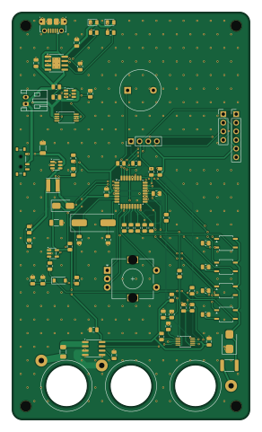
About the Multimetre PCB
Multimetre is an open source AVR/Arduino PCB design by hilham1990, published on GitHub under the CC-BY-NC-4.0 license. It is a 2-layer board measuring 70 × 120 mm, with 82 components from 51 distinct parts.
Its main chip is the ATMEGA328P-AU, from the AVR/Arduino family. Other key parts include the LMV331, ACS712ELCTR-05B-T, 5A, ADS1115IDGS and Buzzer. By type, the board carries 32 resistors, 17 capacitors, 9 ICs, 4 connectors, 4 relays and 3 diodes.
It belongs with the displays & leds and test & measurement designs in this gallery.
From the project
AkademiUsta Multimetre: ATmega328P + 16 bit ADS1115 ADC, OLED ekran ve Li-ion pil ile açık kaynak el multimetresi. KiCad 10 dosyaları, Gerber ve LCSC kodlu BOM. Kart henüz üretilmedi.
ATmega328P tabanlı, ADS1115 16 bit ADC'li, OLED ekranlı ve Li-ion pilli el multimetresi. Bu proje AkademiUsta tarafından sıfırdan yeniden tasarlanmıştır ve eğitim amacıyla açık kaynak olarak paylaşılmaktadır.
- Mod seçimi: döner anahtar yok. 4 × CPC1014N fotoröle, menüde seçilen ölçüm devresini prob hattına bağlar. - Arayüz: 0,96" I2C OLED (H1'e takılır), butonlu döner enkoder (Alps EC11E: çevir = mod, bas = REL), buzzer. - Soketler: Amass 24.302 4 mm güvenlik soketleri kartın kendisinden geçer (kart panel gibi kullanılır). - Güç: 1 hücre Li-ion; TP4056 ile micro-USB'den şarj, DW01A + 8205A…
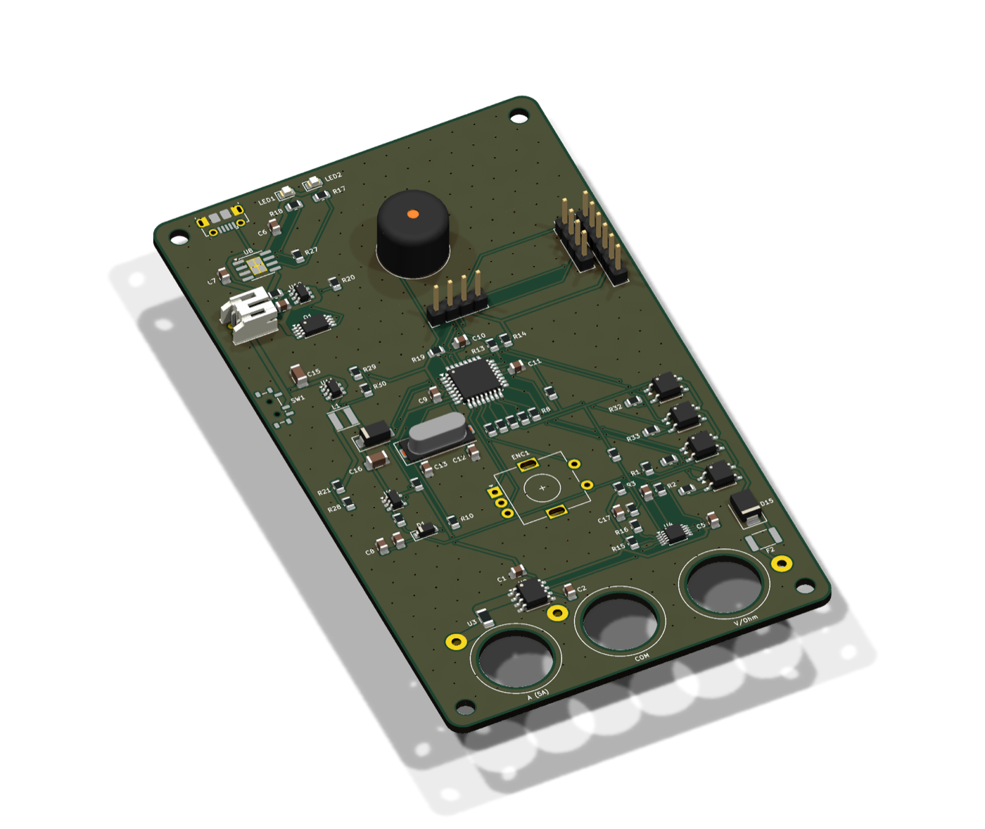
Main components on the Multimetre
Multimetre bill of materials (BOM)
82 components, 51 distinct parts — part numbers from the project's BOM.
| Qty | Part | Footprint | Refs |
|---|---|---|---|
| 1 | LMV331 | SOT-23-5 | U1 |
| 1 | ACS712ELCTR-05B-T | SOIC-8_3.9x4.9mm_P1.27mm | U2 |
| 1 | 5A | Fuse_1206_3216Metric | U3 |
| 1 | ADS1115IDGS | TSSOP-10_3x3mm_P0.5mm | U4 |
| 1 | ATMEGA328P-AU ATmega328P-AU | TQFP-32_7x7mm_P0.8mm | U5 |
| 1 | Buzzer | Buzzer_12x9.5RM7.6 | U6 |
| 1 | TP4056 | SOIC-8-1EP_3.9x4.9mm_P1.27mm_EP2.41x3.3mm_ThermalVias | U8 |
| 1 | DW01A | SOT-23-6 | U10 |
| 1 | MT3608 | SOT-23-6 | U11 |
| 1 | FS8205A | TSSOP-8_4.4x3mm_P0.65mm | Q1 |
| 1 | UART | PinHeader_1x06_P2.54mm_Vertical | X1 |
| 1 | 16MHZ 16MHz | Crystal_SMD_HC49-SD | Y1 |
| 1 | Battery | JST_PH_S2B-PH-K_1x02_P2.00mm_Horizontal | J1 |
| 1 | V/Ohm | BananaSocket_Amass_24.302_M12_Wire | P1 |
| 1 | COM | BananaSocket_Amass_24.302_M12_Wire | P2 |
| 1 | A (5A) | BananaSocket_Amass_24.302_M12_Wire | P3 |
| 1 | EC11E15244G1 | RotaryEncoder_Alps_EC11E-Switch_Vertical_H20mm | ENC1 |
| 1 | 0.1A PTC | Fuse_1812_4532Metric | F2 |
| 1 | OLED_I2C | PinHeader_1x04_P2.54mm_Vertical | H1 |
| 1 | Serial | PinHeader_1x04_P2.54mm_Vertical | H2 |
Show 31 more
| Qty | Part | Footprint | Refs |
|---|---|---|---|
| 1 | ISP | PinHeader_2x03_P2.54mm_Vertical_SMD | H3 |
| 4 | CPC1014N | SOP-4_3.8x4.1mm_P2.54mm | K1, K2, K3, K4 |
| 1 | MSK-12C02 | SW_SPDT_Shouhan_MSK12C02 | SW1 |
| 1 | USB_B_Micro | USB_Micro-B_Molex-105017-0001 | USB2 |
| 2 | LED | LED_0805_2012Metric | LED1, LED2 |
| 1 | 1N4148W | D_SOD-123 | D1 |
| 1 | SS34 | D_SMA | D14 |
| 1 | SMBJ58CA | D_SMB | D15 |
| 1 | 22UH 22uH | L_Taiyo-Yuden_NR-40xx | L1 |
| 6 | 100NF 100nF | C_0805_2012Metric | C1, C4, C9, C10, C11, C14 |
| 1 | 1NF 1nF | C_0805_2012Metric | C2 |
| 4 | 1UF 1uF | C_0805_2012Metric | C3, C5, C8, C17 |
| 2 | 10UF 10uF | C_0805_2012Metric | C6, C7 |
| 2 | 22PF 22pF | C_0805_2012Metric | C12, C13 |
| 2 | 22UF 22uF | C_1206_3216Metric | C15, C16 |
| 1 | 1M | R_0805_2012Metric | R1 |
| 1 | 47K | R_0805_2012Metric | R2 |
| 3 | 2.2K | R_0805_2012Metric | R3, R4, R28 |
| 1 | 2K | R_0805_2012Metric | R5 |
| 1 | 20K | R_0805_2012Metric | R6 |
| 1 | 470K | R_0805_2012Metric | R7 |
| 8 | 1K | R_0805_2012Metric | R8, R17, R18, R20, R31, R32, R33, R34 |
| 8 | 10K | R_0805_2012Metric | R9, R13, R14, R15, R16, R19, R30, R37 |
| 1 | 150R | R_0805_2012Metric | R10 |
| 1 | 330R | R_0805_2012Metric | R11 |
| 1 | 6.8K | R_0805_2012Metric | R21 |
| 1 | 100R | R_0805_2012Metric | R26 |
| 1 | 1.2K | R_0805_2012Metric | R27 |
| 1 | 75K | R_0805_2012Metric | R29 |
| 1 | 4.7K | R_0805_2012Metric | R35 |
| 1 | 22K | R_0805_2012Metric | R36 |
Multimetre design files
The KiCad project lives in the hilham1990/Multimetre repository on GitHub; these links point at the commit this page was built from.
Multimetre: common questions
What microcontroller does the Multimetre use?
The Multimetre is built around the ATMEGA328P-AU, from the AVR/Arduino family.
How big is the Multimetre PCB?
The Multimetre measures 70 × 120 mm, has 2 copper layers and is 1.6 mm thick.
How many components are on the Multimetre?
82 components, from 51 distinct parts, with part numbers taken from the project's own BOM. The full bill of materials is listed on this page.
Where can I download the Multimetre design files?
From the hilham1990/Multimetre repository on GitHub, which has the KiCad layout, the schematic and the BOM; the links under Design files point to each one.
Can I use the Multimetre design in my own project?
It is published under CC-BY-NC-4.0, which limits how it may be reused; read the license before building on it.
Can I test firmware for the Multimetre without the hardware?
Yes. HardLabs builds a simulation of the board from its netlist and BOM, so you can run and debug AVR/Arduino firmware against it before you order a PCB.
Similar boards
 AVR/Arduino
Magspoof
samyk
35 × 29 mm11 parts2LNo license4.2k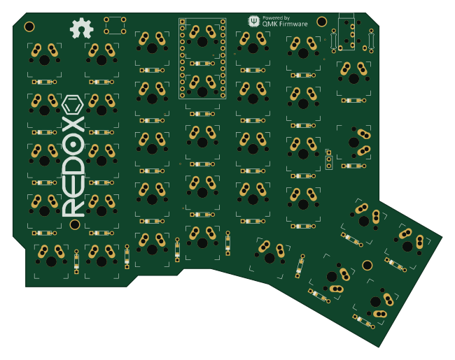 AVR/Arduino
Redox keyboard
mattdibi
162.2 × 126.5 mm77 parts2LMIT2.0k AVR/Arduino
Labrador
espotek-org
36.8 × 34.7 mm75 parts2LNo license1.2k AVR/Arduino
ModuleV450
stuartpittaway
30 × 61.4 mm39 parts2LCC-BY-NC-4.01.1k AVR/Arduino
V4
30 × 50 mm38 parts2LCC-BY-NC-4.01.1k AVR/Arduino
Discipline
coseyfannitutti
304.9 × 122.8 mm170 parts2LCC-BY-NC-4.01.0k