
Line sensor

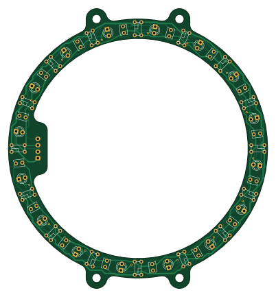
About the Line sensor PCB
Line sensor is an open source PCB design by MUNAKATA-EPC, published on GitHub. It is a 2-layer board measuring 100 × 108 mm, with 49 components from 4 distinct parts.
Other key parts include the S4282-51. By type, the board carries 16 ICs, 16 diodes, 16 capacitors and 1 connector.
It belongs with the sensors designs in this gallery.
From the project
アルテミス2023シーズンのリポジトリです。詳しくはwikiで。
このReadmeでは軽く自チームの紹介がてら結果報告やロボット概要をまとめておきます。 詳しくはいつか出る全国大会の記事で。
Main components on the Line sensor
Line sensor bill of materials (BOM)
49 components, 4 distinct parts.
| Qty | Part | Footprint | Refs |
|---|---|---|---|
| 16 | S4282-51 | Line_sennsor | U1, U2, U3, U4, U5, U6, U7, U8 +8 |
| 1 | Conn_01x04_Female | JST_XH_B4B-XH-A_1x04_P2.50mm_Vertical | J1 |
| 16 | LED | LED_D3.0mm_Clear | D1, D2, D3, D4, D5, D6, D7, D8 +8 |
| 16 | C_Small | C_Disc_D3.8mm_W2.6mm_P2.50mm | C1, C2, C3, C4, C5, C6, C7, C8 +8 |
Line sensor design files
The KiCad project lives in the MUNAKATA-EPC/Artemis_2023 repository on GitHub; these links point at the commit this page was built from.
Line sensor: common questions
How big is the Line sensor PCB?
The Line sensor measures 100 × 108 mm, has 2 copper layers and is 1.6 mm thick.
How many components are on the Line sensor?
49 components, from 4 distinct parts. The full bill of materials is listed on this page.
Where can I download the Line sensor design files?
From the MUNAKATA-EPC/Artemis_2023 repository on GitHub, which has the KiCad layout and the schematic; the links under Design files point to each one.
Can I use the Line sensor design in my own project?
The repository has no license, so all rights stay with MUNAKATA-EPC. Use it as a reference, and ask the author before reusing the design.
More boards in Artemis_2023
 AVR/Arduino
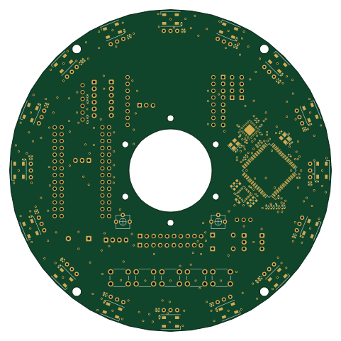
Mainboard
120 × 120 mm151 parts2LNo license2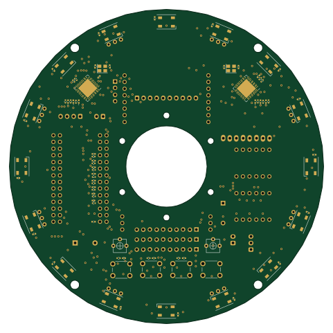 AVR/Arduino
Main board Teensy
120 × 120 mm110 parts2LNo license2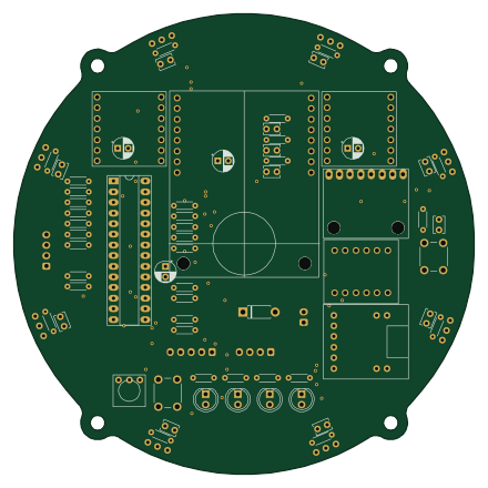 PIC
PICMain board
109.9 × 109.9 mm75 parts2LNo license2
TJ3B
44 parts2LNo license2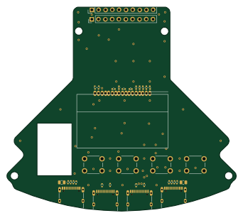 AVR/Arduino
IO Board
85.4 × 76 mm32 parts2LNo license2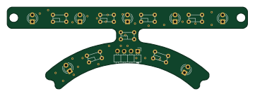
Line sensor front
90 × 30.9 mm22 parts2LNo license2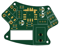
Psu board
57.9 × 45 mm20 parts2LNo license2
AT
15 × 20 mm15 parts2LNo license2
LSM6DS3 Gyro
9.4 × 11.2 mm9 parts2LNo license2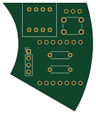
ジャイロ
33.2 × 40 mm7 parts2LNo license2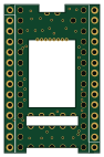 NXP
NXPTeensy4 header breakout
22.9 × 35.6 mm3 parts2LNo license2
Similar boards

Sensor smd
scottbez1
40 × 20 mm5 parts2LApache-2.04.2k
Sensors
StuckAtPrototype
15.2 × 9 mm14 parts4LApache-2.03.8k
Microphone
Mentra-Community
5.5 × 6.1 mm6 parts2LMIT1.2k
TemperaturePCB PANEL
stuartpittaway
116 × 75.5 mm178 parts2LCC-BY-NC-4.01.1k
Pots
shanteacontrols
390 × 93 mm75 parts2LApache-2.0956
ButtonsLEDs
390 × 37 mm82 parts2LApache-2.0956